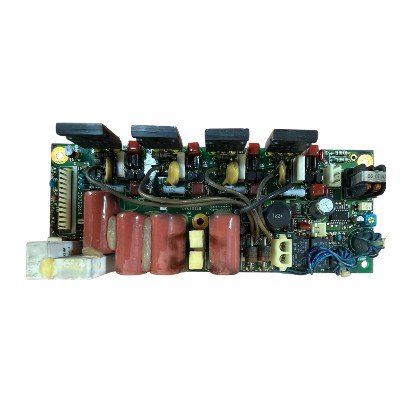
The Furuno Radar FAR2837S Modulator PCB 03P9244 is an original spare electronic board used inside the Furuno FAR‑2837S Marine Radar system. It is part of the radar transmitter section and is responsible for generating and controlling the high-power pulse that the radar sends to the antenna. If this board fails, the radar will usually lose transmission or show weak/unstable echoes.
Technical Specification
1. Main Function
The Modulator PCB generates and controls the high-voltage trigger pulse required to operate the radar magnetron. It synchronizes the transmitter with the radar timing circuits so that microwave pulses are emitted at precise intervals.
2. Role in Radar Transmitter Chain
Typical signal flow:
- Timing/trigger signal from radar processor
- Modulator PCB receives trigger signal
- Pulse-forming network shapes the pulse
- High-voltage switching stage activates
- Magnetron is driven to produce microwave pulse
- Energy travels through waveguide to antenna
3. Major Circuit Sections
- Trigger Input Circuit
Receives timing pulses from the radar control unit.
- Pulse Forming Network (PFN)
A capacitor–inductor network that stores energy and releases it in a controlled pulse.
- High-Voltage Switching Stage
Uses high-power semiconductor devices or switching tubes to discharge the PFN rapidly.
- Magnetron Driver Circuit
Provides the required voltage spike to start magnetron oscillation.
- Protection & Monitoring Circuits
Detects over-current, over-voltage, or trigger failure conditions.
4. Electrical Characteristics (typical for this radar class)
- Pulse repetition frequency: ≈ 500–3000 Hz (range dependent)
- Pulse width: ≈ 0.08–1.2 µs depending on radar mode
- Magnetron drive voltage: several kilovolts
- Timing synchronization: linked to radar range and antenna rotation
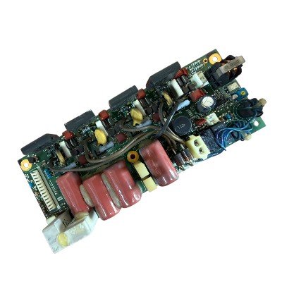
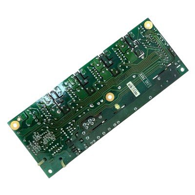
5. Physical Characteristics
- Multi-layer printed circuit board
- High-voltage rated components
- Mounted inside the transmitter unit of the radar cabinet
- Includes connectors for:
- Trigger input
- High-voltage supply
- Magnetron connection
- Monitoring feedback
6. Typical Components on the Board
- High-voltage capacitors
- Pulse transformers
- Fast switching transistors/IGBTs
- Diodes and protection circuits
- Timing control ICs
- High-power resistors
7. Operational Importance
This board directly affects:
- Radar transmission power
- Pulse stability
- Target detection range
- Signal clarity
Failure of the modulator PCB typically results in loss of radar transmission or weak echoes.


There are no reviews yet.