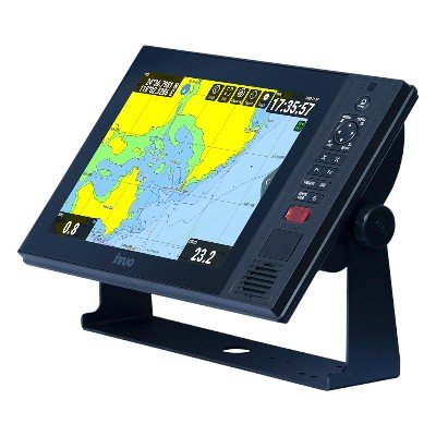
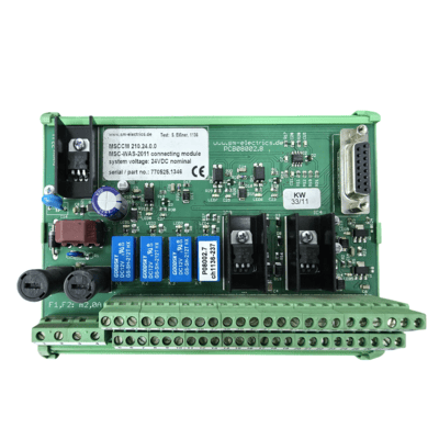
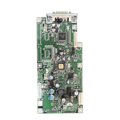
The JRC 901B Option Terminal Board Type No. CQD-2130 (901B-4 7PCNA4016) is a specific component designed for integration within a larger Japan Radio Company (JRC) marine navigation or communication system, most likely a JRC radar or ECDIS (Electronic Chart Display and Information System). This terminal board acts as an expansion or interface unit, providing additional connectivity options or specialized signal processing capabilities that are not standard on the main system board. Its primary role is to facilitate the connection of various peripheral devices, sensors, or other equipment to the JRC system, allowing for the input or output of specific data types (e.g., NMEA 0183, radar video, sync signals, or control lines) that enhance the system’s overall functionality and enable its seamless integration into a comprehensive bridge network. Essentially, it’s an internal circuit board that customizes or extends the I/O capabilities of the primary JRC equipment.
Technical Specification
General:
- Function: Expansion or interface board for a specific JRC marine navigation/communication system. It provides additional input/output capabilities or specialized signal handling.
- Compatibility: Designed exclusively for integration with specific JRC host equipment (e.g., a particular model of JRC radar, ECDIS, or communication system). It is not a standalone device.
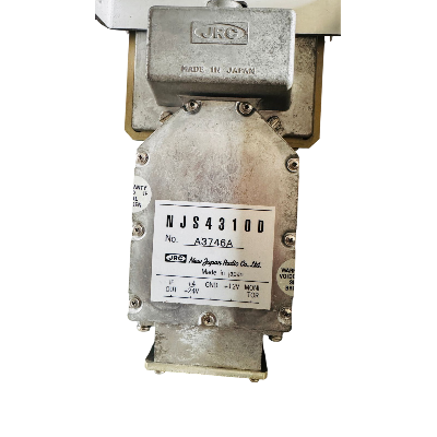
- Part Numbers: CQD-2130, 901B-4, 7PCNA4016 are JRC’s internal identification numbers for this specific PCB assembly.
Electrical & Interfaces (Highly Dependent on Host System):
- Input/Output Types (Potential):
- Serial Data: Likely NMEA 0183 I/O ports for connecting various sensors (GPS, speed log, gyro, AIS) or outputting data to other systems.
- Digital I/O: Discrete digital inputs/outputs for control signals or status indications.
- Analog Inputs: Less common, but possible for specific sensor types.
- Video/Sync Signals: If part of a radar or display system, it could handle video synchronization signals or even specialized video inputs/outputs.
- Ethernet/Proprietary Data Links: Could provide connections for JRC’s proprietary network protocols (e.g., if it’s an interface for a specific JRC network).
- Power Supply: Receives power directly from the main JRC unit it’s installed within. It does not have an independent power input.
- Signal Level: Operates at voltage and current levels compatible with the host JRC system’s internal buses and external marine standard interfaces.
- Protection: Expected to have basic over-current and ESD (Electrostatic Discharge) protection suitable for an internal marine electronic component.
Physical:
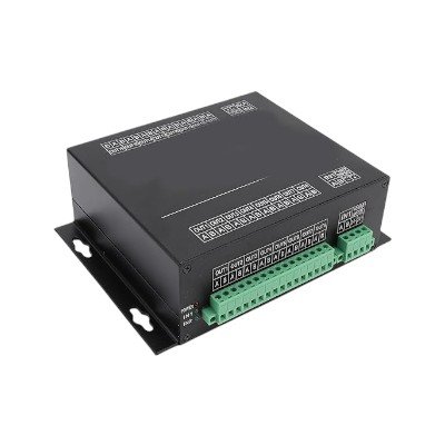
- Form Factor: Printed Circuit Board (PCB) assembly.
- Mounting: Designed for internal mounting within the chassis or enclosure of the compatible JRC main unit. It will have specific mounting holes and connectors to integrate with the host system’s backplane or internal wiring.
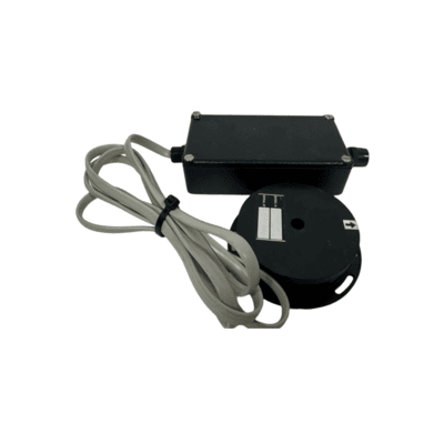
- Connectors: Features various types of connectors (e.g., pin headers, multi-pin shrouded connectors, screw terminals, or coaxial connectors) to interface with internal cabling and external devices.
- Dimensions: Custom-sized to fit the specific JRC equipment bay.
Environmental:
- Operating Environment: As an internal component, it relies on the host system’s enclosure for environmental protection. It’s designed for the typical bridge or equipment room conditions:
- Temperature: Likely −15∘C to +55∘C.
- Humidity: Non-condensing.
- Vibration/Shock: Designed to withstand typical marine vibration and shock experienced inside protected equipment.


There are no reviews yet.