No products in the cart.


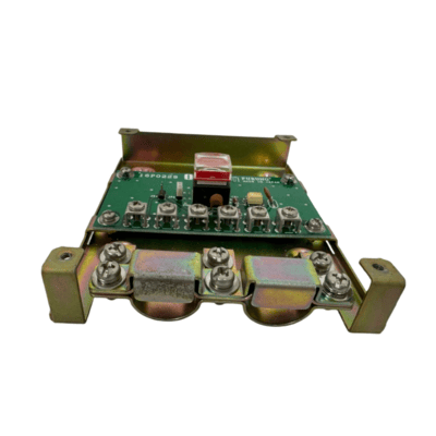
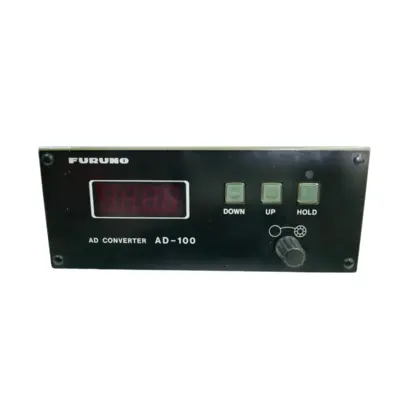
1. Remove four screws from the unit to separate the bottom chassis from the top cover.
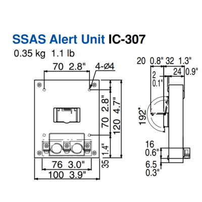
2. Fix the unit to the mounting location with four self-tapping screws (supplied).
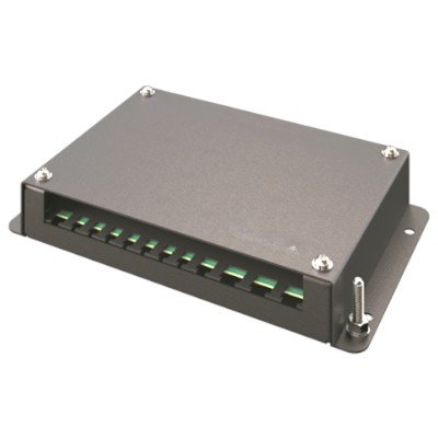
3. The cable can be lead in from the bottom or the rear panel. For rear panel entrance,
change the clamp orientation as follows:
a) Unfasten three screws to remove the cable clamp.
b) Turn the clamp 90 degrees.
c) Refasten the clamp with three screws unfastened at step a) to fix the clamp.
4. Run the cable thru one of the cable entrances and connect it to terminal board.
5. Attach the switch cover as shown below. Note that the cover may be turned 180° to
change cover opening direction.


There are no reviews yet.