No products in the cart.


$1,200.00Earn 1,200 points!
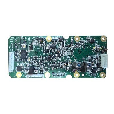
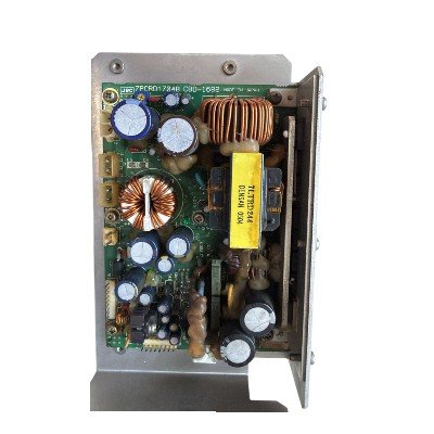
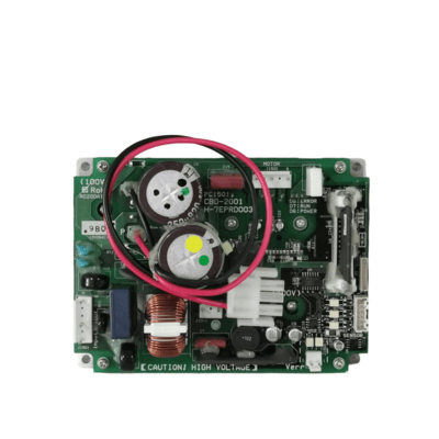
FURUNO FAR 2837 S BAND RECEIVER PCB 03P9335 – A printed circuit board (PCB) used in the FURUNO FAR-2837S S-band marine radar system, typically as part of the radar’s receiver/IF (intermediate frequency) electronics.
Function: This PCB is part of the receiver chain in the FAR-2837S radar — it processes incoming S-band radar echoes captured by the antenna and prepares those signals for further processing by the radar’s main electronics.
Intermediate Frequency (IF) Role: Radar systems often convert high-frequency radar signals to a lower intermediate frequency for filtering and amplification. The 03P9335 board serves in that stage, helping to extract the useful echo information from the raw RF signal.
Signal Path & Functionality
Amplification: Increases the received IF signal level to a usable range for detection.
Filtering: Helps limit noise and adjacent channel interference at IF before digitization/processing.
Video Detection: Converts IF signals to video envelopes for processor interface (in many radar IF board designs).
Control Interfaces: Tuning, gain control, and monitor lines link the board to the main processor unit for automatic gain control (AGC), STC (sensitivity time control), and signal shaping.
Electrical Interfaces
Typically fed with regulated DC supply voltages (e.g., +12 V, +5 V, ± supplies) — common in marine radar electronics for board logic and analog circuits.
Signal outputs include processed IF and video signals to the processor unit.
| Parameter | Typical Inferred Value (Radar IF PCB Class) |
|---|---|
| IF Frequency | ~60 MHz (common internal IF) |
| Gain | Designed to provide adequate signal level to processor — tens of dB (exact not published) |
| Input/Output | IF and video analog signals to processor |
| Power | Board uses regulated DC from radar power subsystem |
| Environment | Marine‑grade rugged PCB construction |


There are no reviews yet.