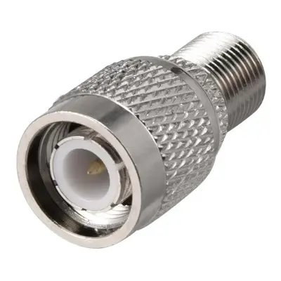
TNC Male to F Female Connector RF Coaxial Coax Adapter is a specialized component used to interface between two distinct types of coaxial cable connectors: the Threaded Neill-Concelman (TNC) and the “F-type” connector. The “TNC Male” end features a secure threaded coupling mechanism with an inner-threaded body and a center pin, characteristic of TNC connectors, which are widely used in robust RF applications requiring high vibration resistance. Conversely, the “F Female” end is a standard, ubiquitous connector primarily associated with consumer video and television applications, such as cable TV, satellite TV, and antennae, identified by its threaded outer shell and a central receptacle designed to receive the solid center conductor of a coaxial cable like RG-6 or RG-59.
This adapter serves as a bridge, allowing devices or cables with a TNC interface to connect to those with an F-type interface, or vice-versa. It facilitates signal transmission between systems that would otherwise be incompatible due to their differing connector standards. While TNC connectors typically maintain a 50 Ohm impedance for most RF communication, F-type connectors are almost exclusively 75 Ohm, optimized for video signals. Therefore, when using this adapter, it’s crucial to be aware of the impedance mismatch, as it can lead to signal reflections and degradation, particularly in applications sensitive to impedance variations. Despite this, these adapters are commonly employed in scenarios where a direct connection is needed, such as connecting a TNC-equipped device to a standard TV antenna, or for testing and prototyping purposes where signal loss due to impedance mismatch is acceptable or accounted for.
Technical Specification
1. Electrical Characteristics:
- Impedance: This is the most critical specification for this adapter.
- TNC side: Typically 50 Ω (Ohms). While 75 Ω TNC connectors exist, they are far less common than 50 Ω versions.
- F-type side: Almost exclusively 75 Ω (Ohms), as it’s designed for broadcast and video applications like cable TV.
- Impedance Mismatch: Due to the inherent difference (50 Ω to 75 Ω), this adapter will introduce an impedance mismatch. This mismatch results in signal reflections (return loss) and, consequently, increased insertion loss, especially at higher frequencies. While a simple adapter is often used, for critical applications, a matching pad (attenuator) would be required to minimize these effects.
- Frequency Range:
- The F-type connector generally performs well up to 1 GHz to 3 GHz for extended range designs, but its primary use is for lower frequencies in TV/video.
- The TNC connector is designed for higher frequencies, typically DC to 6 GHz, and sometimes up to 11 GHz or even 18 GHz for specialized versions.
- The overall frequency range of the adapter will be limited by the lower performing connector, meaning it’s often specified up to 1 GHz to 3 GHz, depending on the quality of the F-type element.
- VSWR (Voltage Standing Wave Ratio): This will likely be higher than for an in-series adapter (e.g., TNC to TNC) due to the impedance mismatch. Expect VSWR values that reflect this, potentially > 1.5:1 or higher, especially as frequency increases.
- Insertion Loss: Will be present due to both the connector’s material/design and the impedance mismatch. Specific values vary, but it will be higher than a matched connection.
- Working Voltage: Typically around 500 V RMS (for the TNC side) and around 400 V RMS (for the F-type side).
- Dielectric Withstanding Voltage: Around 1500 V RMS (TNC) and 1200 V RMS (F-type).
- Insulation Resistance: Generally ≥ 5000 MΩ min.
- Contact Resistance: Low, typically a few milliohms (mΩ) for both center and outer contacts.
2. Mechanical Characteristics:
- Connector 1: TNC Male
- Coupling: Threaded (7/16-28 UNEF thread).
- Center Pin: Protruding.
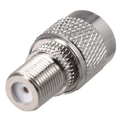
- Connector 2: F Female
- Coupling: Threaded (3/8-32 UNEF thread).
- Center Contact: Receptacle (designed to mate with the solid center conductor of the coaxial cable, which acts as the male pin).
- Body Style: Straight adapter (unless specified as a right-angle variant).
- Durability (Mating Cycles): Typically ≥ 500 cycles for TNC, and ≥ 100 cycles for F-type. The adapter’s overall durability will be limited by the lower value.
- Coupling Nut Retention: Around 100 lbs (444.8 N) min for the TNC side.
3. Material Specifications:
- Body/Shell: Commonly brass with nickel plating for corrosion resistance and durability.
- Center Contact:
- TNC Male: Brass, often gold-plated for optimal conductivity and corrosion resistance.
- F Female: Brass, phosphor bronze, or beryllium copper, often gold or tin-plated.
- Insulator/Dielectric: PTFE (Teflon) is preferred for performance, though polypropylene or Delrin may be used for cost-effectiveness, especially on the F-type side.
4. Environmental Characteristics:
- Operating Temperature Range: Generally wide, such as -55°C to +85°C or even up to +155°C for some materials.
- Vibration and Shock: Designed to withstand typical RF equipment environments, often meeting relevant MIL-STD standards (e.g., MIL-STD-202).
- Corrosion Resistance: Nickel plating provides good corrosion resistance.
Important Consideration (Impedance Mismatch):
It’s crucial to understand that using a 50 Ω TNC to 75 Ω F-type adapter will always involve an impedance mismatch. This means:
- Signal Loss: A portion of the signal will be reflected back towards the source instead of being fully transmitted, leading to a measurable “mismatch loss.”
- VSWR Degradation: The VSWR will be significantly higher than 1:1, indicating poor impedance matching.
- Standing Waves: Reflections can create standing waves on the transmission line, potentially affecting the performance of active components (e.g., amplifiers) connected to the line.
- Reduced Bandwidth: The effective usable frequency range may be reduced compared to perfectly matched connections.


There are no reviews yet.