No products in the cart.


$800.00Earn 800 points!
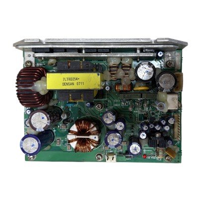
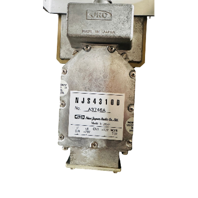
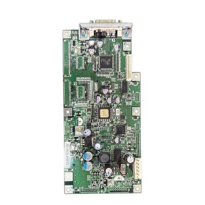
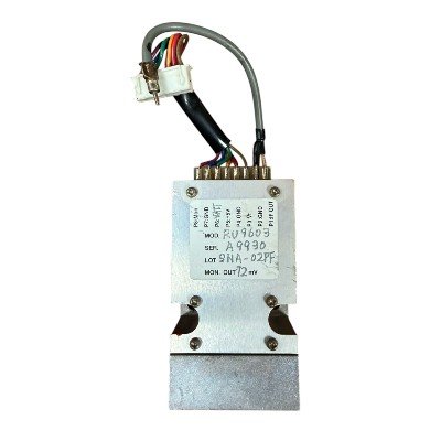
he CBD‑1783 is a dedicated power supply circuit board used in the scanner unit of JRC marine radar systems. Its primary purpose is to convert and regulate electrical power to ensure that the radar’s internal components—such as the antenna motor, receiver, and logic circuits—receive stable and correct voltages.
Purpose: Provides DC power to the radar scanner unit.
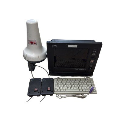
Application: Used in various JRC radar models (e.g., JMA‑610, JMA‑5212/5222, JMR‑611).
Functionality:
Converts input voltage from the ship’s main supply to stable internal voltages.
Supplies power to sub-circuits like motor control, receiver, and processing electronics.
Protects internal circuits against overcurrent or voltage irregularities (depending on design).
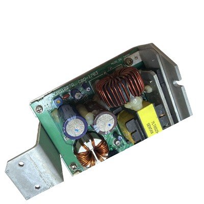
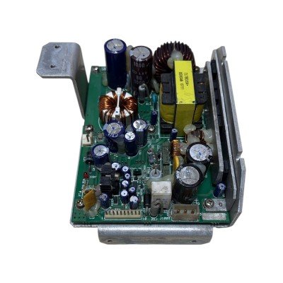
Form Factor: Compact circuit board designed to fit inside the rotating radar scanner head.
The CBD‑1783 is a dedicated power supply circuit board installed inside the scanner unit of certain JRC marine radars (such as the JMR and JMA series). It is designed to convert, regulate, and distribute internal DC power to essential subsystems within the rotating scanner head.
The CBD‑1783 board’s main role is to take the incoming DC power supplied to the scanner unit and provide clean, regulated voltages and reference signals to the internal electronics. This enables proper operation of key radar components such as:
Receiver and transmitter electronics
Motor drive and rotation control
Logic and control circuits
Status feedback and sensor interfaces
Based on service manual interconnection diagrams, the CBD‑1783 board provides multiple regulated output lines, including:
| Pin / Signal | Voltage / Function |
|---|---|
| +15V | Primary logic and motor electronics supply |
| +12V | General auxiliary supply |
| +8V | Specific subsystem power |
| +5V | Digital logic and interface circuits |
| –15V | Negative supply for analog circuits |
| AGND | Analog ground reference |
| GND | Digital ground reference |
| HTER / HVER | Heater or status control signals |
| X1 / X2 | Auxiliary or diagnostic lines |
Exact voltages and usage can vary slightly depending on the radar model and scanner type.
Input Power Source: Receives DC supply from the radar’s main power input (via scanner interconnection harness).
Voltage Regulation: Internally converts the incoming DC to a set of stable voltages with tight regulation required for RF and logic circuits.
Reference Grounding: Provides separate analog and digital ground references to minimize interference between analog and logic subsystems.
Connector Interfaces: Uses multi‑pin connectors (e.g., J1002 and J1003) to link with the receiver circuit, motor control, and other subsystems.


There are no reviews yet.