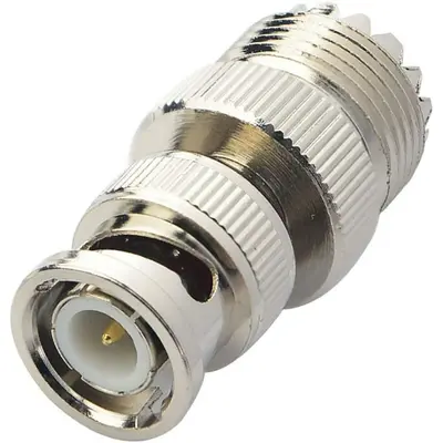
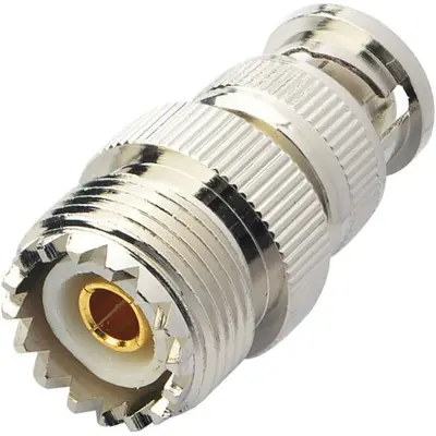
BNC Male Plug to UHF PL-259 Female RF Coaxial Adapter Cable Connector is a specialized inter-series adapter designed to connect devices or cables utilizing the BNC interface with those using the UHF (PL-259/SO-239) interface. This adapter features a BNC male connector, characterized by its quick-connect/disconnect bayonet coupling mechanism, on one end. The other end has a UHF SO-239 (female) connector, which is the receptacle designed to mate with a UHF PL-259 (male) plug. These adapters are commonly used in various radio frequency (RF) applications, particularly in amateur radio (ham radio), CB radio, public address (PA) systems, and older two-way radio equipment, where UHF connectors are prevalent. They facilitate the conversion between the robust, higher-frequency-capable BNC standard and the older, larger UHF standard, allowing for easy adaptation of antennas, test equipment, or coaxial cables with different connector types. While UHF connectors are traditionally considered for frequencies up to 300 MHz, and BNC for up to 4 GHz, this adapter allows interoperability, providing a practical solution for bridging systems with different connector legacies.
Technical Specification
1. Impedance:
- Nominal 50 Ohm: Both BNC and UHF connectors are nominally 50-ohm. However, the UHF connector’s design (lack of constant impedance) makes its impedance matching less precise, especially at higher frequencies. The adapter facilitates connecting two nominally 50-ohm systems.
2. Frequency Range:
- Up to 300 MHz – 500 MHz (typical usable range): While the BNC side can handle frequencies up to 4 GHz or more, the UHF connector’s design causes significant VSWR and insertion loss above approximately 300 MHz to 500 MHz. The adapter’s practical, effective frequency range will be limited by the UHF side’s performance.
- Note: Performance degradation (increased VSWR and insertion loss) will become noticeable and significant as frequencies approach and exceed 300-500 MHz.
3. Electrical Performance:
- Voltage Rating (Working Voltage): Typically 500 V RMS (Root Mean Square) maximum for continuous operation.
- Dielectric Withstanding Voltage: Around 1500 V RMS (at sea level).
- VSWR (Voltage Standing Wave Ratio): This is a critical parameter for RF adapters, indicating signal reflections. Lower values are better.
- At lower frequencies (e.g., < 100 MHz): Typically ≤ 1.3:1 to 1.5:1.
- At higher frequencies (e.g., > 300 MHz): VSWR will significantly increase, potentially to 2.0:1 or higher, due to the non-constant impedance of the UHF connector.
- Insertion Loss: Measures signal power lost through the adapter.
- At lower frequencies: Typically < 0.2 dB.
- At higher frequencies: Insertion loss will increase notably as the frequency approaches and exceeds the UHF connector’s optimal range.
- Insulation Resistance: Minimum 5000 Megohms.
- Contact Resistance:
- Center contact: Typically ≤ 1.5 milliohm.
- Outer contact: Typically ≤ 1.0 milliohm.
- RF Leakage: Generally -55 dB minimum at 3 GHz (though the adapter’s usable frequency is much lower due to the UHF side).
4. Mechanical Specifications:
- Mating Cycles (Durability):
- BNC side: Minimum 500 insertion/extraction cycles.
- UHF side: While not as precisely rated as BNC, generally robust for numerous screw-on cycles.
- Coupling Mechanism:
- BNC Male: Bayonet lock (quarter-turn quick connect/disconnect).
- UHF Female (SO-239): Threaded screw-on for secure, tight connection with PL-259 male plugs.
- Interface Standards: Compliant with relevant MIL-STD or industry standards for both BNC (e.g., MIL-STD-348A) and UHF connectors.
5. Material Specifications:
- Body/Outer Shell: Commonly made of brass with nickel plating. Nickel plating provides good corrosion resistance and durability.
- Center Contact (Pin): Typically brass or beryllium copper, often with gold or silver plating (e.g., 30 µ-in minimum gold plating) for excellent conductivity and resistance to oxidation.
- Insulator/Dielectric: Most often PTFE (Polytetrafluoroethylene or Teflon) for good high-frequency performance and temperature stability, or occasionally Delrin for lower-cost options.
6. Environmental Specifications:
- Operating Temperature Range: Typically -40°C to +85°C (with Delrin) or -55°C to +165°C (with PTFE).
- Moisture Resistance: Designed to withstand typical humidity and environmental exposure.
- Corrosion Resistance: Often tested for salt spray resistance.
- Shock and Vibration: Engineered to withstand reasonable levels of mechanical stress.


There are no reviews yet.