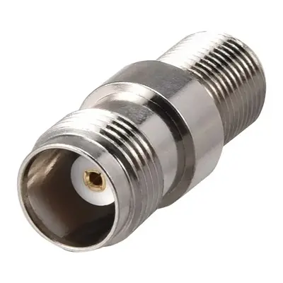
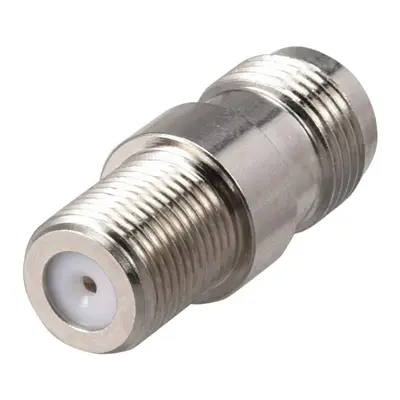
TNC Female to F Type Female Coaxial Cable RF Connector is an adapter designed to bridge connections between two distinct RF connector types: the TNC and the F-Type, both in their female configurations. The TNC Female end features an outer-threaded body and a central receptacle, intended to securely mate with a TNC male plug using its threaded coupling, and is inherently a 50 Ohm connector typically used in professional and military communication systems for its vibration resistance. Conversely, the F Type Female end is a widely adopted consumer-grade connector, characterized by its internal threads and a central receptacle that receives the solid center conductor of a coaxial cable (like RG-6 or RG-59), almost exclusively operating at 75 Ohms for video and broadcast applications such as cable television, satellite, and over-the-air antenna signals.
This adapter serves to allow the interconnection of a TNC male cable or device to an F-type male cable or device. However, it’s crucial to acknowledge that this adapter creates an impedance mismatch due to the differing 50 Ohm (TNC) and 75 Ohm (F-Type) impedances. While it provides mechanical compatibility, this electrical mismatch will inevitably lead to signal reflections and increased insertion loss, which can degrade signal quality, especially at higher frequencies or in sensitive applications. Despite this, such adapters are commonly used in non-critical situations, for temporary connections, or when a direct physical link is necessary and some signal degradation is acceptable, such as adapting a TNC test lead to an F-type port on a consumer device.
Technical Specification
1. Electrical Characteristics:
- Impedance:
- TNC Side: 50 Ω (Ohms). This is the standard impedance for the TNC series.
- F-Type Side: 75 Ω (Ohms). This is the universal impedance for F-Type connectors, designed for video and broadcast applications.
- Impedance Mismatch: This adapter introduces a fundamental impedance mismatch (50Ω to 75Ω). This will inevitably lead to signal reflections and a degradation of electrical performance, particularly at higher frequencies.
- Frequency Range:
- The F-Type connector is typically designed for use up to 1 GHz to 3 GHz.
- The TNC connector is generally specified for higher frequencies, from DC to 6 GHz, and often up to 11 GHz or even 18 GHz for high-performance versions.
- The effective operational frequency range of the adapter will be limited by the lower performing connector (the F-Type) and significantly impacted by the impedance mismatch. Expect reliable performance primarily in the DC to 1 GHz range, with performance degrading noticeably above that.
- VSWR (Voltage Standing Wave Ratio): Due to the impedance mismatch, the VSWR will be significantly higher than for an impedance-matched adapter. Expect values generally > 1.5:1 and potentially much higher (e.g., 2.0:1 or more) depending on the frequency and specific design. A higher VSWR indicates more reflected power and less efficient signal transfer.
- Insertion Loss: The signal loss through the adapter will be present due to both material losses and, more significantly, the loss incurred by the impedance mismatch (mismatch loss). Specific values will vary, but expect it to be higher than an in-series, matched impedance adapter.
- Working Voltage: Typically around 500 V RMS (TNC side) and 400 V RMS (F-Type side).
- Dielectric Withstanding Voltage: Around 1500 V RMS (TNC) and 1200 V RMS (F-Type).
- Insulation Resistance: Generally ≥ 5000 MΩ min.
- Contact Resistance: Low, typically a few milliohms (mΩ) for both center and outer contacts.
2. Mechanical Characteristics:
- Connector 1: TNC Female
- Coupling: Threaded (7/16-28 UNEF thread).
- Center Contact: Receptacle.
- Connector 2: F Type Female
- Coupling: Threaded (3/8-32 UNEF thread).
- Center Contact: Receptacle (designed to mate with the solid center conductor of the coaxial cable, which acts as the male pin).
- Body Style: Straight adapter (unless specified as a right-angle or bulkhead variant).
- Mating Cycles (Durability): Typically ≥ 500 cycles for TNC and ≥ 100 cycles for F-Type. The adapter’s overall durability will be limited by the lower value.
3. Material Specifications:
- Body/Shell: Commonly brass with nickel plating for corrosion resistance and durability.
- Center Contact:
- TNC Female: Beryllium copper or brass, often gold-plated for optimal conductivity and corrosion resistance.
- F Type Female: Brass, phosphor bronze, or beryllium copper, often tin or nickel-plated.
- Insulator/Dielectric: PTFE (Teflon) is preferred for performance on the TNC side; Delrin, polypropylene, or similar plastics may be used for the F-type side.
4. Environmental Characteristics:
- Operating Temperature Range: Generally wide, such as -55°C to +85°C.
- Vibration and Shock: Designed to withstand typical RF equipment environments.
- Corrosion Resistance: Nickel plating provides good corrosion resistance.
Important Note on Impedance Mismatch:
It is crucial for users to understand that this adapter is a mechanical adapter only and does not provide impedance transformation. The 50Ω to 75Ω impedance mismatch will lead to:
- Significant return loss, meaning a portion of the signal will be reflected back to the source.
- Increased insertion loss beyond what a perfectly matched connection would have.
- Potential for signal distortion, especially for digital or wideband signals.


There are no reviews yet.