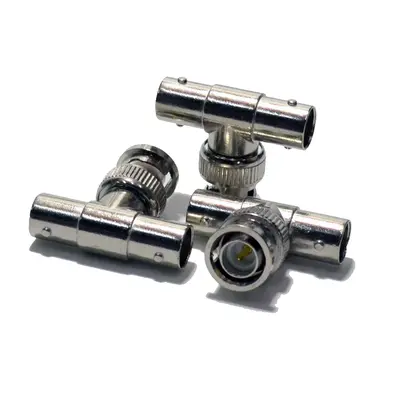
BNC 1 Male to 2 Female T Type Splitter is a common coaxial adapter designed to efficiently distribute or combine signals within a BNC-based system. As its name suggests, it features a single BNC male connector on one end, intended to plug into a BNC female port on a device or cable, and two BNC female connectors arranged in a “T” configuration on the other ends. This allows for the simultaneous connection of two separate BNC-terminated cables or devices to a single source or destination. Predominantly found in 50-ohm impedance for applications such as older Ethernet networks (10BASE2), test and measurement equipment, and general RF signal distribution, 75-ohm versions are also available for video surveillance (CCTV) and broadcast setups. The robust bayonet coupling mechanism characteristic of BNC ensures a quick, secure, and reliable connection, minimizing signal degradation while providing flexibility in cabling configurations. These splitters are essential tools for expanding connectivity, branching signals, or creating temporary tap points in various coaxial environments.
Technical Specification
1. Impedance:
- 50 Ohm: This is the most prevalent impedance for BNC T-splitters. It’s commonly used in applications like 10BASE2 (Thin Ethernet) networking, general radio frequency (RF) signal routing, and various test and measurement setups. Maintaining 50-ohm impedance throughout the system is crucial for minimizing signal reflections and maximizing power transfer.
- 75 Ohm: Less common but available for specific video distribution applications, such as CCTV systems, where matching the 75-ohm impedance of video coaxial cables (e.g., RG-59, RG-6) is essential for signal integrity, especially for higher resolution or longer cable runs.
2. Frequency Range:
- For 50 Ohm versions: Typically operates from DC (Direct Current) up to 4 GHz. While the BNC connector itself can handle up to 4 GHz or higher, the “T” configuration can introduce some performance degradation at the very highest frequencies, making the effective usable range slightly less than a straight adapter.
- For 75 Ohm versions: Generally, from DC up to 1 GHz or 2 GHz. High-quality versions designed for professional video (e.g., HD-SDI, 3G-SDI) might support frequencies up to 3 GHz or 6 GHz, but this is less common for simple T-splitters due to potential signal reflections.
3. Electrical Performance:
- Voltage Rating (Working Voltage): Typically around 500 V RMS (Root Mean Square) maximum.
- Dielectric Withstanding Voltage: Approximately 1500 V RMS (at sea level).
- VSWR (Voltage Standing Wave Ratio): This is a critical parameter for splitters as it indicates signal reflections. Lower values are better.
- For 50 Ohm: Typically 1.3:1 maximum up to 4 GHz.
- For 75 Ohm: Can be around 1.2:1 to 1.5:1 maximum up to 1-2 GHz.
- Note: In a T-splitter, the VSWR can be more sensitive to the load conditions on the two female ports. Proper termination (e.g., with 50-ohm or 75-ohm terminators on unused ports) is crucial to maintain good VSWR.
- Insertion Loss: Measures signal power lost as it passes through the splitter. Because it’s a passive splitter, there will inherently be some loss as the power is divided.
- Typically < 0.5 dB at lower frequencies (e.g., 1 GHz), increasing with frequency. This loss is in addition to the theoretical -3dB (50%) loss for splitting power equally between two paths.
- Insulation Resistance: Minimum 5000 Megohms.
- Contact Resistance:
- Center contact: Typically ≤ 1.5 milliohm.
- Outer contact: Typically ≤ 1.0 milliohm.
- RF Leakage: Measures how much RF energy leaks from the connector. Typically -55 dB minimum at 3 GHz.
4. Mechanical Specifications:
- Mating Cycles (Durability): Designed for a minimum of 500 insertion/extraction cycles.
- Coupling Mechanism: BNC’s characteristic bayonet lock provides a quick and secure connection.
- Interface Specification: Compliant with standards like MIL-STD-348A for physical dimensions and mating interface.
- Dimensions: Compact, T-shaped form factor with dimensions typically around 32mm (Length) x 27mm (Width) x 14mm (Height), though this can vary slightly between manufacturers.
5. Material Specifications:
- Body/Outer Shell: Most commonly made of brass with nickel plating for good conductivity, durability, and corrosion resistance. Some variations might use zinc alloy.
- Center Contact (Pin): Usually brass or beryllium copper, with gold or silver plating (e.g., 30 µ-in minimum gold plating) for optimal conductivity and resistance to oxidation.
- Insulator/Dielectric: Often PTFE (Teflon) for excellent high-frequency performance and temperature stability, or Delrin (Acetal resin) for more cost-effective options.
6. Environmental Specifications:
- Operating Temperature Range: Typically -40°C to +85°C (for Delrin insulators) or -55°C to +165°C (for PTFE insulators).
- Moisture Resistance: Designed to withstand standard levels of humidity and splash exposure.
- Corrosion Resistance: Often tested for resistance to salt spray.
- Shock and Vibration: Engineered to withstand typical levels of mechanical shock and vibration as per relevant industry standards.


There are no reviews yet.