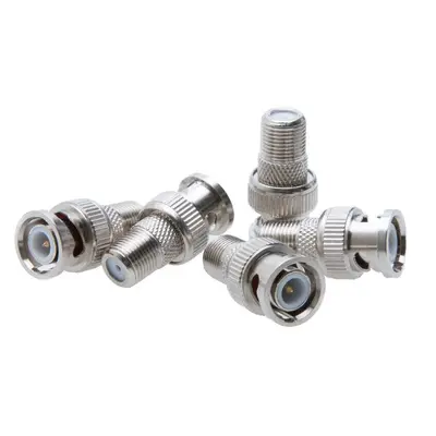
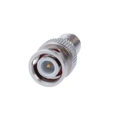
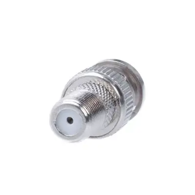
BNC Male to F-Type Female Coaxial Cable Adapter Converter Connector is a specialized component designed to seamlessly connect devices or cables with differing BNC and F-Type interfaces. This adapter typically features a BNC male connector on one end, which is characterized by its quick-connect/disconnect bayonet coupling mechanism, and an F-Type female connector on the other, identifiable by its threaded screw-on design. Predominantly, these adapters are 75-ohm impedance, making them ideal for video applications such as CCTV surveillance systems, DVRs, satellite dishes, cable television (CATV), and antennas. They provide a practical solution for integrating professional video equipment, which often uses BNC, with consumer-grade systems or existing cabling that utilizes F-Type connections (like RG-59 or RG-6 coaxial cables). Constructed with durable materials such as nickel-plated brass and often featuring gold-plated center pins, these adapters ensure reliable signal transmission with minimal signal loss and corrosion resistance. Their straight, in-line configuration provides a compact and secure connection, making them a valuable tool for technicians and DIY enthusiasts alike for adapting between various RF and video systems.
Technical Specification
1. Impedance:
- 75 Ohm: This is the standard impedance for video applications (e.g., CCTV, broadcast, cable TV) and is what these adapters are almost exclusively designed for. Using a 50-ohm BNC with a 75-ohm F-Type would result in significant signal degradation due to impedance mismatch.
- Note: While a 50-ohm BNC male to 75-ohm F-Type female adapter exists for specific applications, the vast majority for common use are 75-ohm on both sides. If the BNC side is 50 Ohm and the F-Type is 75 Ohm, the adapter acts as an impedance transformer, which would have different performance characteristics (e.g., higher insertion loss, specific frequency response).
2. Frequency Range:
- Typically from DC (Direct Current) up to 1 GHz or 2 GHz. High-quality adapters designed for SDI (Serial Digital Interface) or HD-SDI might support frequencies up to 3 GHz, 6 GHz, or even 12 GHz for 12G-SDI applications. The practical upper limit is often determined by the F-Type connector’s performance.
3. Electrical Performance:
- Voltage Rating (Working Voltage): Typically 500 V RMS (Root Mean Square) maximum.
- Dielectric Withstanding Voltage: Around 1500 V RMS.
- VSWR (Voltage Standing Wave Ratio): A measure of signal reflection. Lower values are better.
- For 75 Ohm: Typically ≤ 1.22:1 up to 1 GHz, and can be around 1.3:1 to 1.5:1 at higher frequencies (e.g., 2 GHz or 3 GHz). True high-performance versions aim for lower VSWR.
- Insertion Loss: Measures signal power lost as it passes through the adapter. This should be minimal.
- Typically < 0.2 dB up to 3 GHz. Lower values are better for signal integrity.
- Insulation Resistance: Minimum 5000 Megohms.
- Contact Resistance:
- Center contact: Typically ≤ 1.5 milliohm.
- Outer contact: Typically ≤ 1.0 milliohm.
- RF Leakage: Typically -55 dB maximum at 3 GHz.
4. Mechanical Specifications:
- Mating Cycles (Durability): Designed for a minimum of 500 insertion/extraction cycles.
- BNC Coupling Mechanism: Bayonet lock (quarter-turn).
- F-Type Coupling Mechanism: Threaded screw-on.
- Interface Dimensions: Generally compliant with MIL-STD-348A for the BNC side and relevant F-Type standards.
- Force to Engage/Disengage: Specified in pounds or inch-pounds for both connectors.
5. Material Specifications:
- Body/Outer Shell: Commonly nickel-plated brass for corrosion resistance and durability. Some budget versions may use zinc alloy.
- Center Contact (Pin): Usually brass or beryllium copper, often with gold or silver plating for excellent conductivity and corrosion resistance (e.g., 30 µ-in gold plating).
- Insulator/Dielectric: Typically PTFE (Polytetrafluoroethylene, or Teflon) for high-frequency performance and temperature stability, or Delrin (Acetal resin) for less demanding applications.
6. Environmental Specifications:
- Operating Temperature Range: Common range is -40°C to +85°C for standard adapters, or -55°C to +165°C for those with PTFE insulators.
- Moisture Resistance: Designed to withstand specified levels of humidity and moisture.
- Corrosion Resistance: Often tested against salt spray.
- Vibration and Shock: Designed to tolerate typical levels of mechanical stress found in their intended applications.


There are no reviews yet.