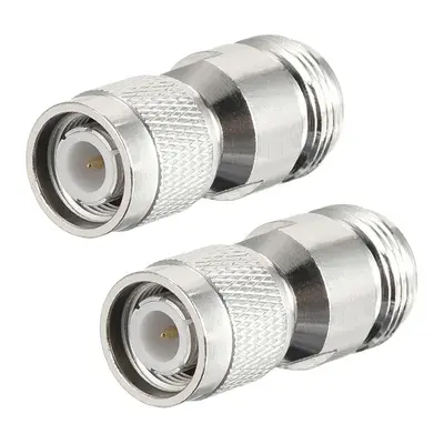
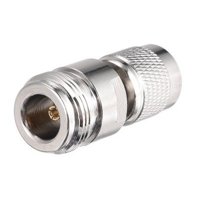
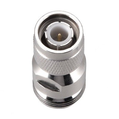
TNC Male to N Type Female Coaxial Cable RF Connector is an adapter designed to interface two distinct types of 50-Ohm radio frequency (RF) coaxial connectors: the Threaded Neill-Concelman (TNC) and the N-Type. The TNC Male end features a secure threaded coupling with an inner-threaded body and a center pin, characteristic of TNCs, which are widely used in professional and military RF applications requiring robust, vibration-resistant connections. The N Type Female end is a larger, equally robust, threaded connector with an outer-threaded coupling nut and a central receptacle, renowned for its excellent performance in high-frequency and high-power applications such as radar, wireless infrastructure, and test equipment.
This adapter serves a crucial role in enabling connectivity between devices or cable assemblies equipped with TNC male connectors and those with N Type female connectors. Both TNC and N-Type connectors are predominantly 50-Ohm impedance, ensuring that this adapter facilitates an electrically matched connection. This minimizes signal reflections and insertion loss, which are critical for maintaining signal integrity and efficient power transfer in RF systems.
Consequently, this connector is invaluable in a variety of scenarios, including adapting TNC-equipped antennas to N-Type radio equipment, integrating different components within a wireless network, or in test and measurement setups where a reliable and low-loss transition between these two common 50-Ohm RF connector standards is necessary. Its design ensures a durable and high-performance link, making it a staple in professional RF installations.
Technical Specification
1. Electrical Characteristics:
- Impedance: 50 Ω (Ohms). Both TNC and N-Type connectors are predominantly 50 Ohm, ensuring an impedance-matched connection when using this adapter. This is crucial for minimizing signal reflections and maximizing power transfer.
- Frequency Range: Typically DC to 6 GHz, but high-performance versions can extend up to 11 GHz or even 18 GHz, limited by the specific design and quality of the components. N-Type connectors generally offer superior performance at the higher end of this spectrum compared to TNC.
- VSWR (Voltage Standing Wave Ratio): A measure of impedance matching. For a high-quality adapter, typical VSWR is ≤ 1.25:1 to 1.35:1 max across its specified frequency range. Lower values indicate better matching and less signal reflection.
- Insertion Loss: The amount of signal power lost through the adapter. Being an in-series adapter designed for matching impedances, insertion loss is typically very low, often ≤ 0.1 dB to 0.2 dB max at the upper frequency limits.
- Working Voltage: Typically 500 V RMS for the TNC side and 1000 V RMS for the N-Type side, or a combined rating that reflects the lower of the two.
- Dielectric Withstanding Voltage: Generally around 1500 V RMS (TNC) to 2500 V RMS (N-Type) at sea level.
- Insulation Resistance: Usually ≥ 5000 MΩ (Megohms) min.
- Contact Resistance: Very low for efficient signal transfer.
- Center Contact: ≤ 1.0 mΩ to 1.5 mΩ max
- Outer Contact: ≤ 0.2 mΩ to 3.0 mΩ max
2. Mechanical Characteristics:
- Connector 1: TNC Male
- Coupling: Threaded (7/16-28 UNEF thread).
- Center Pin: Protruding.
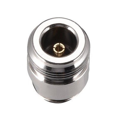
- Connector 2: N Type Female
- Coupling: Threaded (5/8-24 UNEF or similar).
- Center Contact: Receptacle.
- Body Style: Straight adapter (unless specified as a right-angle or bulkhead variant).
- Mating Cycles (Durability): Typically ≥ 500 cycles for both TNC and N-Type, ensuring long-term reliability.
- Coupling Nut Retention: Strong retention, often 100 lbs (444.8 N) min for TNC and similar or higher for N-Type.
3. Material Specifications:
- Body/Shell: Primarily brass, with common platings including nickel, silver, or sometimes passivated stainless steel for corrosion resistance and durability.
- Center Contact:
- TNC Male: Brass, with gold plating (e.g., 50 microinches gold over nickel) for optimal conductivity and corrosion resistance.
- N Type Female: Beryllium copper or brass, also typically with gold plating.
- Insulator/Dielectric: PTFE (Polytetrafluoroethylene), often referred to as Teflon, due to its excellent electrical properties, low dielectric constant, and high-temperature stability.
- Gasket (for environmental sealing): Silicone rubber, used in weatherproof versions.
4. Environmental Characteristics:
- Operating Temperature Range: Broad, typically -55°C to +85°C, and for military-grade or high-performance versions, it can extend to -65°C to +165°C.
- Vibration: Designed to withstand significant vibration, often meeting or exceeding MIL-STD-202 standards (e.g., Method 204).
- Shock: Resistant to mechanical shock (e.g., MIL-STD-202, Method 213).
- Corrosion Resistance: High resistance to environmental corrosion, often tested by salt spray (e.g., MIL-STD-202, Method 101).
- Moisture Resistance: Capable of operating in humid or wet conditions, commonly tested to MIL-STD-202, Method 106.


There are no reviews yet.