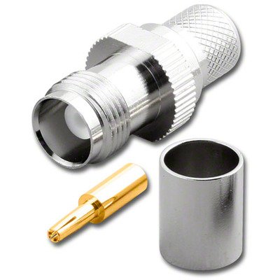
This product is a TNC Female Connector specifically designed for crimp termination onto larger 50 Ohm coaxial cables such as RG8U, RG213, LMR400, LMR400UF, RFC400, RFC400DB, and RFC400UF. As a TNC (Threaded Neill-Concelman) connector, it features a robust threaded coupling mechanism, which ensures a highly secure, vibration-resistant, and weatherproof connection, crucial for maintaining signal integrity in demanding radio frequency (RF) applications. Being a “Female” connector, it contains an outer barrel with internal threading and a central receptacle designed to precisely mate with the center pin of a male TNC plug. The “crimp” termination method involves compressing a metal ferrule around the cable’s outer braid and jacket, while the center conductor is typically soldered or sometimes crimped, creating a durable mechanical and low-resistance electrical bond. The broad compatibility with “400-series” cables (like LMR400, RFC400, and their variants) and traditional thick cables (RG8U, RG213) signifies its application in systems requiring high power handling, lower signal loss over longer distances, and robust performance, making it ideal for applications such as cellular base stations, high-gain antennas, broadband wireless, amateur radio, and other demanding RF installations.
Technical Specification
1. Electrical Specifications:
- Impedance: 50Ω (Ohms) – This is the standard impedance for all the listed cables and TNC connectors in this category.
- Frequency Range: Typically 0 to 6 GHz (Gigahertz). Some high-quality or specialized versions can extend up to 11 GHz or 12 GHz.
- Voltage Rating:
- Working Voltage: Often higher than for smaller connectors, typically around 1000VRMS (Volts Root Mean Square) at sea level, reflecting the higher power handling of the compatible cables.
- Dielectric Withstanding Voltage (DWV): Often around 2500VRMS to 4000VRMS (at sea level).
- VSWR (Voltage Standing Wave Ratio):
- Excellent performance, typically <1.2:1 to 1.3:1 at lower frequencies (e.g., up to 3 GHz).
- Will degrade gracefully at the higher end of its specified frequency range.
- Contact Resistance:
- Center Contact: Typically ≤1.0 m$\Omega$ (milliohms).
- Outer Contact: Typically ≤0.5 m$\Omega$.
- Insulation Resistance: Typically ≥5000 M$\Omega$ (Megaohms).
- Insertion Loss: Very low, typically <0.05 dB at lower frequencies, increasing marginally with frequency.
2. Mechanical Specifications:
- Connector Type: TNC Female Jack/Receptacle.
- Coupling Mechanism: 7/16−28UNS−2B internal threading, ensuring a very secure and vibration-proof connection.
- Termination Style: Primarily Crimp for the outer ferrule (braid and jacket). The center contact is often Solder for these larger cables (RG8U, RG213) to ensure a robust and low-resistance connection for the larger central conductor, though crimp-style center pins are also available for some LMR-400 specific connectors.
- Cable Compatibility: Designed for specific outer diameters and dielectric diameters to ensure a proper fit for:
- RG8U & RG213: These are older, standard large-diameter (approx. 0.405 inch / 10.3 mm OD) 50 Ohm cables with solid PE dielectric and braided shield.
- LMR400, LMR400UF, RFC400, RFC400DB, RFC400UF: These are modern low-loss 400-series cables (approx. 0.405 inch / 10.3 mm OD) with foamed dielectric and often foil/braid double shielding. The “UF” indicates Ultra-Flexible.
- Durability (Mating Cycles): Typically ≥500 cycles, indicating a long operational lifespan.
- Cable Retention Force: High, designed to withstand significant axial pull force due to the larger cable size and robust crimp.
3. Material & Plating:
- Body: High-quality Brass, chosen for its excellent machinability and structural integrity.
- Body Plating: Typically Nickel (often over copper flash) for superior corrosion resistance, wear resistance, and a durable finish. Some might be Silver plated for even better RF performance, though less common for general-purpose TNC.
- Center Contact: Beryllium Copper or Phosphor Bronze for the female receptacle, selected for its spring characteristics, high conductivity, and resistance to deformation after repeated mating.
- Center Contact Plating: Gold (typically 30-50 microinches over nickel) for excellent conductivity, low contact resistance, and long-term corrosion prevention.
- Insulator: PTFE (Polytetrafluoroethylene, e.g., Teflon) is almost exclusively used due to its outstanding dielectric properties, low RF loss, and wide operating temperature range.
- Gasket/Seal (if weatherproof): Silicone rubber or other suitable elastomeric material for IP rating compliance.
4. Environmental Specifications:
- Temperature Range (Operating): Typically wide, from −65∘C to +165∘C (limited by the dielectric and jacket material of the cable, and the connector’s internal components).
- Corrosion Resistance: High resistance to salt spray, humidity, and other environmental factors (e.g., meeting MIL-STD-202, Method 101, Test Condition B).
- Vibration: Designed to maintain stable electrical and mechanical connections under specified vibration levels (e.g., MIL-STD-202, Method 204, Test Condition B).
- Shock: Designed to withstand mechanical shock (e.g., MIL-STD-202, Method 213, Test Condition I).
- Weatherproof/Waterproof: Many are designed to be weatherproof or meet IP67 (Ingress Protection) when properly mated and installed, suitable for outdoor or harsh environments.
5. Recommended Tooling:
- Crimp Tool: Requires a heavy-duty crimp tool with specific hexagonal die sizes (e.g., 0.429″ / 10.9mm for LMR-400 / RG8 / RG213 ferrules, and often a smaller hex for the center pin if it’s crimp-type, or a soldering iron for solder pins).
- Cable Stripping Tool: A precision multi-stage stripping tool is essential to prepare the cable layers to the exact dimensions specified by the connector manufacturer.


There are no reviews yet.