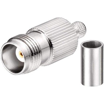
TNC Female Connector designed for crimp termination onto various 50 Ohm coaxial cables, specifically listed as RG58, RG142, RG223, RG400, LMR195, and RFC195. As a TNC (Threaded Neill-Concelman) connector, it utilizes a robust threaded coupling mechanism, which ensures a secure and stable connection that resists vibration and provides superior performance at higher frequencies compared to its bayonet-style counterpart, the BNC. Being a “Female” connector, it features an outer barrel with internal threading and a central receptacle designed to receive the pin of a male TNC plug. The “crimp” termination method indicates that the connector attaches to the cable by compressing a metal ferrule around the cable’s outer braid and jacket, along with typically crimping or soldering the center conductor, creating a reliable and durable electrical and mechanical bond. The specified cable compatibility (RG58, RG142, RG223, RG400, LMR195, RFC195) confirms its versatility for a range of 50 Ohm coaxial cables, from common flexible types like RG58 and LMR195/RFC195 to high-performance, double-shielded, and high-temperature cables such as RG142, RG223, and RG400, making it suitable for diverse radio frequency applications requiring a robust, electrically efficient, and physically secure connection.
Technical Specification
1. Electrical Specifications:
- Impedance: 50Ω (Ohms). This is the standard impedance for TNC connectors and all the listed compatible cables.
- Frequency Range: Typically 0 to 6 GHz for standard commercial-grade connectors. High-performance or precision TNC connectors can operate reliably up to 11 GHz or even 15 GHz.
- Voltage Rating:
- Working Voltage: Often around 500VRMS (Volts Root Mean Square) at sea level.
- Dielectric Withstanding Voltage (DWV): Typically 1500VRMS (at sea level) for one minute without breakdown.
- VSWR (Voltage Standing Wave Ratio):
- Generally excellent at lower frequencies, often <1.3:1 to 1.2:1 up to 3 GHz.
- May increase slightly at higher frequencies within its operating range.
- Contact Resistance:
- Center Contact: Typically ≤1.5 m$\Omega$ (milliohms).
- Outer Contact: Typically ≤1.0 m$\Omega$.
- Insulation Resistance: Typically ≥5000 M$\Omega$ (Megaohms).
- Insertion Loss: Very low, typically <0.1 dB at lower frequencies, increasing marginally with frequency.
2. Mechanical Specifications:
- Connector Type: TNC Female Jack/Receptacle.
- Coupling Mechanism: 7/16−28UNS−2B internal threading (designed to mate with the male plug’s external threading).
- Termination Style: Crimp (for the outer ferrule/braid). The center contact is typically crimp, but some designs might use solder for the center pin, especially for certain cable types.
- Cable Compatibility: Designed for coaxial cables with specific dimensions for:
- Inner Conductor: (Crimp or Solder attachment).
- Dielectric Diameter: Must match the connector’s internal design.
- Outer Braid/Shield: Crimped by the ferrule.
- Outer Jacket Diameter: Must fit within the ferrule/body.
- Compatible Cables: RG58, RG142, RG223, RG400, LMR195, RFC195 (or equivalent low-loss 195-series cables).
- Durability (Mating Cycles): Typically ≥500 cycles, ensuring long-term reliability.
- Cable Retention Force: Varies depending on cable type and crimp quality, but designed to hold the cable securely.
3. Material & Plating:
- Body: Commonly Brass, known for its machinability and strength.
- Body Plating: Often Nickel or sometimes Tin-Nickel for excellent corrosion resistance and durability.
- Center Contact: Typically Beryllium Copper or Phosphor Bronze for the female receptacle, chosen for its springiness, conductivity, and resistance to fatigue.
- Center Contact Plating: Usually Gold (often 50 µin over nickel) for superior conductivity, minimal contact resistance, and long-term corrosion prevention, especially crucial for repeated mating cycles.
- Insulator: PTFE (Polytetrafluoroethylene, e.g., Teflon) is the most common dielectric material due to its excellent RF properties, low loss, and wide temperature range.
- Gasket/Seal (if waterproof): Silicone rubber or similar elastomer for environmental sealing.
4. Environmental Specifications:
- Temperature Range (Operating): Typically −65∘C to +165∘C (the range can vary slightly depending on the specific plastic and plating materials used).
- Corrosion Resistance: High resistance to salt spray, humidity, and other environmental factors, especially important in marine or outdoor applications.
- Vibration: Designed to maintain connection integrity under typical vibration conditions (due to the threaded coupling).
- Shock: Engineered to withstand reasonable mechanical shock.
5. Tooling:
- Crimp Tool: Requires a specific crimping tool with the correct die set that matches the ferrule size and, if applicable, the center pin crimp size for the specified cable types.
- Stripping Tool: A precision cable stripping tool is essential to prepare the cable ends with accurate dimensions for proper assembly.


There are no reviews yet.