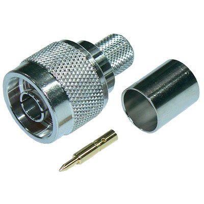
N-Type Male Connector designed for RG8U, RG213, LMR400, LMR400UF, RFC400, RFC400DB, and RFC400UF cables is a robust, threaded 50 Ohm coaxial connector widely utilized in demanding RF applications such as cellular infrastructure, Wi-Fi systems, broadcast, and high-power radio communication. This male connector (plug) is specifically engineered to accommodate the larger diameters and often double-braided constructions of these 50 Ohm impedance cables, which are known for their low-loss characteristics and higher power handling capabilities. Termination typically involves either a solder connection for the center conductor and a clamp mechanism for the outer braid and jacket, or a combination of solder for the center and a crimp ferrule for the braid and jacket. The N-Type’s secure threaded coupling ensures excellent mechanical stability, superior electrical performance with minimal signal loss at frequencies extending into the microwave range, and reliable weatherproofing, making it ideal for both indoor and harsh outdoor installations.
Technical Specification
1. Electrical Characteristics:
- Impedance: 50 Ohms (Ω)
- Frequency Range: DC to 6 GHz (standard), often rated up to 11 GHz or 18 GHz for precision versions (though cable limits may apply).
- VSWR (Voltage Standing Wave Ratio):
- Typically ≤1.25:1 up to 3 GHz
- ≤1.35:1 up to 6 GHz
- ≤1.50:1 up to 11 GHz (for higher frequency designs)
- Insertion Loss: Low, typically ≤0.1 dB at 3 GHz
- Return Loss: High, typically ≥20 dB at 3 GHz
- Working Voltage: 1000 V RMS (at sea level)
- Dielectric Withstanding Voltage: 2500 V RMS (at sea level)
- Insulation Resistance: ≥5000 M$\Omega$
- Contact Resistance:
- Center Contact: ≤1.0 m$\Omega$ (initial)
- Outer Contact: ≤0.2 m$\Omega$ (initial)
2. Mechanical Characteristics:
- Connector Type: N-Type Male (Plug)
- Mating Interface: N-Type (Per MIL-STD-348B/304 or IEC 61169-16)
- Cable Compatibility: Specifically designed for larger diameter 50 Ohm coaxial cables:
- RG-8/U
- RG-213/U
- LMR®-400 (and equivalents like RFC®-400)
- LMR®-400-UF (UltraFlex) / RFC®-400UF
- RFC®-400DB (Direct Burial)
- Note: These cables have similar dielectric and outer braid dimensions, allowing for common connector designs.
- Cable Attachment Method:
- Center Contact: Solder (most common for reliability with these larger conductors)
- Outer Braid/Jacket:
- Clamp Type: The cable’s jacket and braid are secured by a threaded clamping nut and compression washer(s).
- Crimp Type: A crimp ferrule is used over the cable’s braid and jacket, compressed with a specific hex crimp die (e.g., 0.429″ or 0.475″).
- Both methods provide robust mechanical and electrical connections.
- Coupling Mechanism: Threaded Coupling (5/8″-24 UNEF-2A thread)
- Coupling Nut Retention: ≥100 lbs (445 N)
- Cable Retention (Axial Force): ≥80 lbs (356 N) for LMR-400/RG213 (varies by termination method)
- Durability (Mating Cycles): ≥500 cycles
3. Materials and Finishes:
- Body: Brass, Nickel Plated (typically 100 µin min for corrosion resistance)
- Center Contact: Brass or Beryllium Copper, Gold Plated (typically 3-50 µin over Nickel for optimal conductivity and wear resistance)
- Insulator: PTFE (Polytetrafluoroethylene / Teflon) for excellent electrical properties and high temperature performance.
- Gasket (if weatherproof): Silicone Rubber
- Crimp Ferrule (for crimp types): Annealed Copper or Brass, Nickel Plated
4. Environmental Characteristics:
- Operating Temperature Range: −65∘C to +165∘C (with PTFE insulator)
- Thermal Shock: MIL-STD-202, Method 107, Condition B
- Vibration: MIL-STD-202, Method 204, Condition D
- Mechanical Shock: MIL-STD-202, Method 213, Condition I
- Moisture Resistance: MIL-STD-202, Method 106
- Corrosion (Salt Spray): MIL-STD-202, Method 101, Condition B (48 hours)


There are no reviews yet.