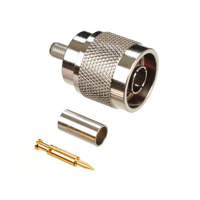
N-Type Male Crimp Connector designed for RG-58/U and LMR®-195 cables is a robust 50 Ohm coaxial connector featuring a threaded coupling mechanism for secure and stable connections, widely used in wireless communication, cellular, and Wi-Fi applications. This male connector (plug) is specifically engineered to accommodate the smaller diameters of RG-58/U and LMR®-195 coaxial cables, which are both 50 Ohm impedance types. The “crimp” termination method signifies that the cable’s outer braid is secured to the connector body using a crimping tool and a dedicated crimp ferrule, while the center conductor is typically soldered or sometimes crimped. This combination provides a reliable, low-loss electrical connection and excellent mechanical stability, making it suitable for both indoor and outdoor environments due to the N-Type’s inherent weather resistance when properly installed.
Technical Specification
1. Electrical Characteristics:
- Impedance: 50 Ohms (Ω)
- Frequency Range: DC to 6 GHz (or higher, typically up to 11 GHz for precision N-types, but practical performance often limited by cable type). For RG58/LMR195, effective performance is usually strong up to 3-4 GHz.
- VSWR (Voltage Standing Wave Ratio):
- Typically ≤1.30:1 up to 3 GHz
- ≤1.50:1 up to 6 GHz
- Insertion Loss: Low, typically ≤0.15 dB at 3 GHz
- Return Loss: Typically ≥18 dB at 3 GHz
- Working Voltage: 1000 V RMS (at sea level)
- Dielectric Withstanding Voltage: 2500 V RMS (at sea level)
- Insulation Resistance: ≥5000 M$\Omega$
- Contact Resistance:
- Center Contact: ≤1.0 m$\Omega$ (initial)
- Outer Contact: ≤0.2 m$\Omega$ (initial)
2. Mechanical Characteristics:
- Connector Type: N-Type Male (Plug)
- Mating Interface: N-Type (Per MIL-STD-348B/304 or IEC 61169-16)
- Cable Compatibility: Specifically designed for:
- RG-58/U
- LMR®-195 (or equivalent such as RFC-195, CFD-195)
- Note: These cables have similar outer diameters and dielectric sizes, allowing for common crimp and center pin designs.
- Cable Attachment Method:
- Center Contact: Solder (most common for reliable contact) or Crimp
- Outer Braid/Jacket: Crimp (using a specific crimp ferrule and hex die size for RG58/LMR195, typically 0.213″ or 0.255″)
- Coupling Mechanism: Threaded Coupling (5/8″-24 UNEF-2A thread)
- Coupling Nut Retention: ≥100 lbs (445 N)
- Cable Retention (Axial Force): ≥40 lbs (178 N) for RG58/LMR195
- Durability (Mating Cycles): ≥500 cycles
3. Materials and Finishes:
- Body: Brass, Nickel Plated (typically 100 µin min)
- Center Contact: Brass or Phosphor Bronze, Gold Plated (typically 3-50 µin over Nickel)
- Insulator: PTFE (Polytetrafluoroethylene / Teflon) for high performance and temperature stability
- Gasket (if weatherproof): Silicone Rubber
- Crimp Ferrule: Annealed Copper or Brass, Nickel Plated
4. Environmental Characteristics:
- Operating Temperature Range: −65∘C to +165∘C (with PTFE insulator)
- Thermal Shock: MIL-STD-202, Method 107, Condition B
- Vibration: MIL-STD-202, Method 204, Condition D
- Mechanical Shock: MIL-STD-202, Method 213, Condition I
- Moisture Resistance: MIL-STD-202, Method 106
- Corrosion (Salt Spray): MIL-STD-202, Method 101, Condition B (48 hours)
- Weatherproofing: When properly assembled, often rated for outdoor use (IP67 or similar, depending on design and sealing).


There are no reviews yet.