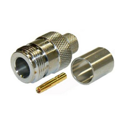
N-Type Female Connector designed for RG8U, RG213, LMR400, LMR400UF, RFC400, RFC400DB, and RFC400UF cables is a robust, threaded 50 Ohm coaxial connector primarily used as a panel mount, bulkhead, or inline adapter in high-frequency applications such as cellular base stations, broadcast equipment, and industrial RF systems. This female connector (jack or receptacle) is specifically engineered to interface with the larger diameter and low-loss characteristics of these 50 Ohm impedance cables. It features an internal threaded coupling for secure mating with an N-Type male connector and a recessed center socket to receive the male’s pin. The termination method for these heavy-duty cables typically involves either soldering the center conductor and using a clamp mechanism for the outer braid/jacket or employing a dedicated crimp ferrule, ensuring a highly reliable electrical connection with minimal signal degradation and excellent mechanical strength, crucial for the demanding environments where these cables and connectors are deployed.
Technical Specification
1. Electrical Characteristics:
- Impedance: 50 Ohms (Ω)
- Frequency Range: DC to 6 GHz (standard), often rated up to 11 GHz or 18 GHz for precision versions. The practical limit for reliable low-loss operation with these cables is typically up to 6 GHz.
- VSWR (Voltage Standing Wave Ratio):
- Typically ≤1.25:1 up to 3 GHz
- ≤1.35:1 up to 6 GHz
- ≤1.50:1 up to 11 GHz (for higher frequency designs)
- Insertion Loss: Low, typically ≤0.1 dB at 3 GHz
- Return Loss: High, typically ≥20 dB at 3 GHz
- Working Voltage: 1000 V RMS (at sea level)
- Dielectric Withstanding Voltage: 2500 V RMS (at sea level)
- Insulation Resistance: ≥5000 M$\Omega$
- Contact Resistance:
- Center Contact: ≤1.0 m$\Omega$ (initial)
- Outer Contact: ≤0.2 m$\Omega$ (initial)
- RF Leakage: Typically ≥−90 dB at 3 GHz (for well-designed versions)
2. Mechanical Characteristics:
- Connector Type: N-Type Female (Jack / Receptacle)
- Mating Interface: N-Type (Per MIL-STD-348B/304 or IEC 61169-16)
- Mounting Styles (Common for Female):
- Panel Mount (e.g., 2-hole, 4-hole flange mount, bulkhead)
- Chassis Mount
- Inline / Cable End
- Cable Compatibility: Specifically designed for larger diameter 50 Ohm coaxial cables:
- RG-8/U
- RG-213/U
- LMR®-400 (and equivalents like RFC®-400)
- LMR®-400-UF (UltraFlex) / RFC®-400UF
- RFC®-400DB (Direct Burial)
- Cable Attachment Method:
- Center Contact: Solder (most common for reliability with these larger conductors)
- Outer Braid/Jacket:
- Clamp Type: The cable’s jacket and braid are secured by a threaded clamping nut and compression washer(s).
- Crimp Type: A crimp ferrule is used over the cable’s braid and jacket, compressed with a specific hex crimp die (e.g., 0.429″ or 0.475″).
- Coupling Mechanism: Internal Threaded Coupling (to mate with 5/8″-24 UNEF-2B thread of male connector)
- Cable Retention (Axial Force): ≥80 lbs (356 N) for LMR-400/RG213 (varies by termination method and connector design)
- Durability (Mating Cycles): ≥500 cycles
3. Materials and Finishes:
- Body: Brass, Nickel Plated (typically 100 µin min for corrosion resistance)
- Center Contact: Beryllium Copper or Phosphor Bronze, Gold Plated (typically 3-50 µin over Nickel for optimal conductivity and wear resistance)
- Insulator: PTFE (Polytetrafluoroethylene / Teflon) for excellent electrical properties and high temperature performance.
- Gasket (if weatherproof): Silicone Rubber (for panel mount or inline versions designed for environmental sealing)
- Crimp Ferrule (for crimp types): Annealed Copper or Brass, Nickel Plated
4. Environmental Characteristics:
- Operating Temperature Range: −65∘C to +165∘C (with PTFE insulator)
- Thermal Shock: MIL-STD-202, Method 107, Condition B
- Vibration: MIL-STD-202, Method 204, Condition D
- Mechanical Shock: MIL-STD-202, Method 213, Condition I
- Moisture Resistance: MIL-STD-202, Method 106
- Corrosion (Salt Spray): MIL-STD-202, Method 101, Condition B (48 hours)
- Weatherproofing: When properly assembled, often provides excellent ingress protection (e.g., IP67 or greater), making them suitable for harsh outdoor environments.


There are no reviews yet.