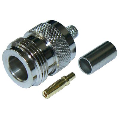
N-Type Female Captivated Connector designed for RG58, RG142, RG223, RG400, LMR195, and RFC195 cables is a 50 Ohm coaxial connector featuring a robust threaded coupling mechanism. This female connector (jack or receptacle) is primarily intended for panel or bulkhead mounting, distinguishing itself with a “captivated” center contact. This means the center contact is securely fixed and cannot move axially, ensuring a consistent electrical connection and preventing push-back or withdrawal during repeated mating cycles. Engineered to precisely fit the smaller diameters of these 50 Ohm cables, termination typically involves crimping the outer braid and either soldering or crimping the center conductor. The captivated design provides superior mechanical stability and enhanced reliability, crucial for applications in wireless communications, test and measurement equipment, and other RF systems where frequent connections, environmental resilience, and long-term performance are critical.
Technical Specification
1. Electrical Characteristics:
- Impedance: 50 Ohms (Ω)
- Frequency Range: DC to 6 GHz (standard), with some precision versions up to 11 GHz or 18 GHz. Practical performance with these smaller cables is often optimal up to 3-4 GHz.
- VSWR (Voltage Standing Wave Ratio):
- Typically ≤1.30:1 up to 3 GHz
- ≤1.50:1 up to 6 GHz
- Insertion Loss: Low, typically ≤0.15 dB at 3 GHz
- Return Loss: High, typically ≥18 dB at 3 GHz
- Working Voltage: 1000 V RMS (at sea level)
- Dielectric Withstanding Voltage: 2500 V RMS (at sea level)
- Insulation Resistance: ≥5000 M$\Omega$
- Contact Resistance:
- Center Contact: ≤1.0 m$\Omega$ (initial)
- Outer Contact: ≤0.2 m$\Omega$ (initial)
- RF Leakage: Typically ≥−90 dB at 3 GHz (for well-designed versions)
2. Mechanical Characteristics:
- Connector Type: N-Type Female (Jack / Receptacle)
- Mating Interface: N-Type (Per MIL-STD-348B/304 or IEC 61169-16)
- Center Contact Type: Captivated (mechanically fixed, preventing axial movement, ensuring consistent contact over mating cycles).
- Mounting Styles: Primarily designed for panel or bulkhead mounting (e.g., 2-hole flange, 4-hole flange, threaded bulkhead with nut).
- Cable Compatibility: Specifically designed for smaller diameter 50 Ohm coaxial cables:
- RG-58/U
- RG-142/U
- RG-223/U
- RG-400/U
- LMR®-195 (and equivalents like RFC®-195, CFD-195)
- Note: These cables have similar outer diameters and dielectric sizes, allowing for common crimp/termination tooling.
- Cable Attachment Method:
- Center Contact: Solder (most common for reliable contact) or Crimp
- Outer Braid/Jacket: Crimp (using a specific crimp ferrule and hex die size, typically around 0.213″ to 0.255″ depending on cable and connector design).
- Coupling Mechanism: Internal Threaded Coupling (to mate with 5/8″-24 UNEF-2B thread of male connector)
- Cable Retention (Axial Force): ≥40 lbs (178 N) for RG58/LMR195 (varies by termination method)
- Durability (Mating Cycles): ≥500 cycles
3. Materials and Finishes:
- Body: Brass, Nickel Plated (typically 100 µin min for corrosion resistance)
- Center Contact: Beryllium Copper or Phosphor Bronze, Gold Plated (typically 3-50 µin over Nickel for optimal conductivity and wear resistance)
- Insulator: PTFE (Polytetrafluoroethylene / Teflon) for excellent electrical properties and high temperature performance.
- Gasket (for sealed versions): Silicone Rubber (for weatherproof panel mount types)
- Crimp Ferrule: Annealed Copper or Brass, Nickel Plated
4. Environmental Characteristics:
- Operating Temperature Range: −65∘C to +165∘C (with PTFE insulator)
- Thermal Shock: MIL-STD-202, Method 107, Condition B
- Vibration: MIL-STD-202, Method 204, Condition D
- Mechanical Shock: MIL-STD-202, Method 213, Condition I
- Moisture Resistance: MIL-STD-202, Method 106
- Corrosion (Salt Spray): MIL-STD-202, Method 101, Condition B (48 hours)
- Weatherproofing: When properly assembled and installed (especially panel-mount types with gaskets), provides good ingress protection (e.g., IP65 or IP67).


There are no reviews yet.