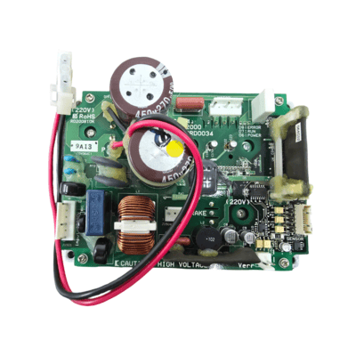
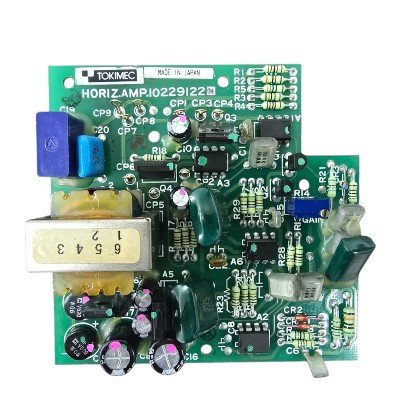
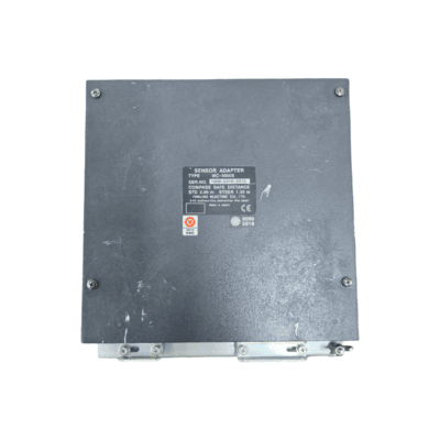
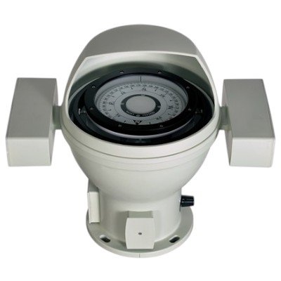
The JRC Radar JMA-9122 CBD-2000 Scanner Motor Power PCB (Part Number H-7EPRD0034) is a crucial electronic component within the scanner unit of the JRC JMA-9122 series marine radar system.
This Printed Circuit Board (PCB) is specifically responsible for supplying and regulating the electrical power to the scanner motor of the radar antenna. The scanner motor is what rotates the radar antenna (the “scanner”) on top of the vessel, allowing it to transmit and receive radar signals in a full 360-degree sweep.
In essence, the H-7EPRD0034 PCB acts as the power control center for the scanner’s mechanical operation. Without this board functioning correctly, the radar antenna would not be able to rotate, and thus, the radar system would be unable to scan the surrounding environment and provide a radar image. It ensures the motor receives the correct voltage and current for reliable and consistent rotation, which is vital for accurate radar performance.
Technical Specification
General:
- Part Number: H-7EPRD0034
- Module Name: CBD-2000 (often referred to as the Motor Drive PCB)
- Application: Scanner unit motor power control for JRC JMA-9100/9122 series radars (also compatible with JMA-7100 and JMR-72/92 series).
Electrical Specifications (Inferred/Common):
- Input Voltage: This PCB receives power from the main radar power supply unit. For the JMA-9122 radar series, the overall system typically operates on:
- AC 110V (AC 100 to 115V) and/or
- AC 230V (AC 220 to 240V)
- Frequency: 50/60Hz, 1-phase
- The PCB itself will likely rectify and regulate this input to deliver the specific DC voltage(s) required by the scanner motor.
- Output Voltage/Current to Motor:
- Given some listings mentioning “220V Motor Drive” for this PCB, it strongly suggests the output voltage to the motor is 220V DC (or a rectified and controlled AC equivalent if the motor is AC). However, some JRC scanner motors are brushless DC motors, which would imply a DC output.
- The current capability would be designed to drive the scanner motor, which is typically a brushless motor. The overall radar consumption for the scanner unit can reach up to 1700VA (max), with an average around 350VA, so the PCB handles a significant amount of power.
- Motor Type: Designed for the brushless motor used in the CBD-2000 scanner unit.
- Control Signals: Receives control signals from the main radar processing unit (e.g., NDC-1399-9) to control motor speed (RPM) and potentially start/stop functions.
- Protection Circuitry: Likely includes overcurrent protection, overvoltage protection, and thermal protection for both the PCB components and the motor.
Performance Characteristics (Related to the scanner unit):
- Rotation Speed(s): The PCB facilitates the scanner unit’s rotation at specified speeds, typically:
- 24 RPM (revolutions per minute)
- 48 RPM (for high-speed versions)
- Some scanner motors are also specified for 27 RPM. The CBD-2000 supports multiple speeds.
- Modulation: As it controls a power supply for a radar component, it likely integrates with the radar’s solid-state modulator circuit.
Physical:
- Type: Printed Circuit Board (PCB)
- Connectors: Features various connectors for power input, motor output, and control signals from other radar units.
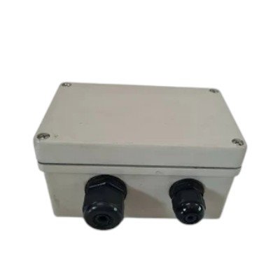
- Location: Installed within the CBD-2000 scanner unit (antenna unit) itself.
Environmental:
- Operating Temperature: Must withstand the harsh conditions inside the scanner unit, which can be exposed to outdoor marine temperatures (e.g., -25°C to +55°C).
- Humidity: Designed for high humidity environments (e.g., 93% @ 40°C).


There are no reviews yet.