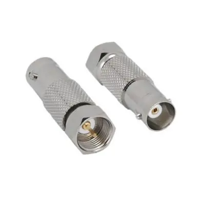
F-Type Coax Coaxial Male to BNC Female Connector is an adapter designed to bridge the connection between two distinct types of coaxial interfaces: the threaded F-Type male connector and the bayonet-locking BNC female connector. This adapter features a male F-Type connector on one end, which is commonly found on consumer-grade video equipment, satellite receivers, cable modems, and antennas, and is designed to screw onto an F-Type female port on a cable (like RG-6 or RG-59). The other end features a BNC female connector, which is prevalent in professional video, security camera systems (CCTV), broadcast equipment, and some RF applications. Predominantly, these adapters are 75-ohm impedance, making them perfectly suited for video signals, allowing users to integrate BNC-terminated devices into systems that primarily utilize F-Type connections, or vice-versa. Constructed from durable materials, often nickel-plated brass, they ensure reliable signal transmission and offer a convenient solution for adapting different coaxial standards without the need for complex rewiring.
Technical Specification
1. Impedance:
- 75 Ohm: This is the overwhelmingly dominant impedance for this type of adapter. Both F-Type and BNC connectors used in video applications (such as CCTV, CATV, satellite, and broadcast) are 75-ohm. Maintaining this impedance is crucial for proper signal transmission and minimizing reflections in video systems.
- Note: While BNC connectors can also be 50-ohm for RF/data applications, an F-Type to BNC adapter is almost exclusively for 75-ohm video systems. An impedance mismatch (e.g., trying to use a 75-ohm adapter with a 50-ohm BNC cable) would lead to significant signal degradation.
2. Frequency Range:
- Typically from DC (Direct Current) up to 1 GHz or 2 GHz. High-quality adapters designed for higher bandwidth video applications (e.g., HD-SDI, 3G-SDI) might support frequencies up to 3 GHz, 6 GHz, or even 12 GHz, matching the capabilities of modern F-Type connectors and high-performance 75-ohm BNC connectors.
3. Electrical Performance:
- Voltage Rating (Working Voltage): Typically around 500 V RMS (Root Mean Square) maximum.
- Dielectric Withstanding Voltage: Approximately 1500 V RMS (at sea level).
- VSWR (Voltage Standing Wave Ratio): A measure of signal reflection; lower values are better.
- For 75 Ohm: Typically ≤ 1.25:1 up to 1 GHz, possibly increasing slightly at higher frequencies (e.g., 1.3:1 at 2 GHz, 1.5:1 at 3 GHz for standard models). High-performance versions will have much lower VSWR.
- Insertion Loss: Measures signal power lost as it passes through the adapter. Should be minimal.
- Typically < 0.2 dB up to 3 GHz. The goal is always to have as little loss as possible.
- Insulation Resistance: Minimum 5000 Megohms.
- Contact Resistance:
- Center contact: Typically ≤ 1.5 milliohm.
- Outer contact: Typically ≤ 1.0 milliohm.
- RF Leakage: Typically -55 dB minimum at 3 GHz.
4. Mechanical Specifications:
- Mating Cycles (Durability): Designed for a minimum of 500 insertion/extraction cycles for the BNC side, and often a similar range for the F-Type side, though F-Type is generally considered less robust for frequent disconnections.
- BNC Coupling Mechanism: Bayonet lock (quarter-turn) for quick connect/disconnect.
- F-Type Coupling Mechanism: Threaded screw-on for a secure, tight connection.
- Interface Specification: Generally compliant with relevant standards for both BNC (e.g., MIL-STD-348A) and F-Type connectors (e.g., SCTE standards).
- Dimensions: A compact, in-line adapter that provides direct conversion.
5. Material Specifications:
- Body/Outer Shell: Most commonly made of brass with nickel plating. Nickel plating provides excellent corrosion resistance and durability, which is important for both indoor and outdoor (e.g., antenna) applications.
- Center Contact (Pin): Typically brass or beryllium copper, often with gold or silver plating (e.g., 30 µ-in minimum gold plating). Plating ensures excellent conductivity and corrosion resistance.
- Insulator/Dielectric: Commonly PTFE (Polytetrafluoroethylene or Teflon) for superior high-frequency performance and temperature stability, or Delrin (Acetal resin) for more cost-effective options in less demanding environments.
6. Environmental Specifications:
- Operating Temperature Range: Common range is -40°C to +85°C (with Delrin) or -55°C to +165°C (with PTFE).
- Moisture Resistance: Designed to withstand various levels of humidity and moisture exposure.
- Corrosion Resistance: Often tested for salt spray resistance.
- Shock and Vibration: Engineered to withstand typical levels of mechanical shock and vibration as per relevant industry standards.


There are no reviews yet.