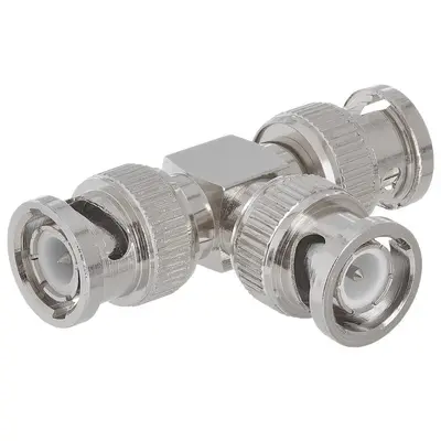
BNC Male To 2xBNC Male Adapter is a specialized coaxial connector designed to take a single BNC female input and split it into two BNC male outputs, or conversely, to combine two BNC female inputs into a single BNC male output. This adapter features one BNC male connector at its base, which plugs into a female BNC port, and then branches out into two additional BNC male connectors. These two male ends are often positioned parallel to each other or in a “Y” configuration. Primarily used in video (CCTV, broadcast) and RF/test & measurement applications, this adapter allows for the convenient duplication of a signal or the connection of multiple BNC female-terminated cables to a single BNC male-terminated port. It maintains the secure, quick-connect/disconnect bayonet coupling mechanism of BNC connectors and is available in both 50-ohm and 75-ohm impedance versions to suit various system requirements, providing flexibility in cable management and signal distribution
Technical Specification
1. Impedance:
- 50 Ohm: Most commonly used for general RF, data communication, and test & measurement applications. It’s crucial for maintaining signal integrity in 50-ohm systems.
- 75 Ohm: Used specifically for video applications (e.g., CCTV, broadcast video, SDI signals) to match the impedance of 75-ohm coaxial cables (RG-59, RG-6).
- Selecting the correct impedance is paramount to prevent signal reflections and loss.
2. Frequency Range:
- For 50 Ohm versions: Typically designed for DC (Direct Current) up to 4 GHz. The splitting nature can introduce some performance limitations at the very highest frequencies compared to straight adapters.
- For 75 Ohm versions: Generally operates from DC up to 1 GHz or 2 GHz. High-quality versions tailored for HD/3G/6G-SDI might extend to 3 GHz, 6 GHz, or even 12 GHz, but detailed specifications for such high frequencies should be verified.
3. Electrical Performance:
- Voltage Rating (Working Voltage): Typically 500 V RMS (Root Mean Square) maximum.
- Dielectric Withstanding Voltage: Approximately 1500 V RMS (at sea level).
- VSWR (Voltage Standing Wave Ratio): A critical measure of signal reflections; lower values indicate better impedance matching and less signal loss.
- For 50 Ohm: Typically ≤ 1.3:1 maximum up to 4 GHz.
- For 75 Ohm: Typically ≤ 1.25:1 to 1.5:1 maximum up to 3 GHz.
- Note: In a splitter configuration, VSWR performance is highly dependent on the load conditions on the output ports. Proper termination (e.g., with 50-ohm or 75-ohm terminators on unused ports) is often necessary for optimal performance.
- Insertion Loss: Measures signal power lost through the adapter. As a passive splitter, there is an inherent theoretical power division loss (e.g., approximately -3 dB per output for equal power distribution).
- Total Insertion Loss (including power division and adapter loss): Typically < 3.5 dB to 4.0 dB at lower frequencies (e.g., 1 GHz) from input to each output, increasing with frequency. This actual loss includes the theoretical -3dB power split.
- Isolation (between output ports): For splitters, this indicates how well signals on one output port are prevented from affecting the other output port.
- Typically > 20 dB to 25 dB at lower frequencies (e.g., 100 MHz).
- Insulation Resistance: Minimum 5000 Megohms.
- Contact Resistance:
- Center contact: Typically ≤ 1.5 milliohm.
- Outer contact: Typically ≤ 1.0 milliohm.
- RF Leakage: Typically -55 dB minimum at 3 GHz.
4. Mechanical Specifications:
- Mating Cycles (Durability): Designed for a minimum of 500 insertion/extraction cycles per port.
- Coupling Mechanism: All three ports utilize the standard BNC bayonet lock (quarter-turn) for quick and secure connection.
- Configuration: One BNC male connector branching into two BNC male connectors (often in a “Y” or parallel configuration).
- Interface Specification: Compliant with standards like MIL-STD-348A for physical dimensions and mating interface.
- Dimensions: Compact, often Y-shaped or block-shaped depending on the design. Specific dimensions vary by manufacturer.
5. Material Specifications:
- Body/Outer Shell: Most commonly made of brass with nickel plating. Nickel plating provides good corrosion resistance, durability, and shielding.
- Center Contact (Pin): Typically brass or beryllium copper, with gold or silver plating (e.g., 30 µ-in minimum gold plating) for excellent conductivity and resistance to oxidation.
- Insulator/Dielectric: Often PTFE (Polytetrafluoroethylene, or Teflon) for superior high-frequency performance and temperature stability, or Delrin (Acetal resin) for more cost-effective options.
6. Environmental Specifications:
- Operating Temperature Range: Common range is -40°C to +85°C (with Delrin insulators) or -55°C to +165°C (with PTFE insulators).
- Moisture Resistance: Designed to withstand specified levels of humidity and moisture.
- Corrosion Resistance: Often tested against salt spray.
- Shock and Vibration: Engineered to withstand typical levels of mechanical stress and vibration.


There are no reviews yet.