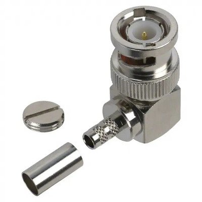
BNC Male Right Angle Connector, designed for use with RG58, RG142, RG223, RG400, LMR195, and RFC195 coaxial cables, is a specialized 50 Ohm RF connector that offers a 90-degree bend in its form factor. This right-angle design is crucial in applications where space is limited, cable bending radius needs to be minimized, or a neat, flush connection to a device is required, preventing strain on the cable and the equipment’s port. As a male connector, it features a bayonet-style coupling nut for quick and secure attachment to female BNC jacks. These connectors typically employ crimp or solder termination for the center pin and a crimp method for the outer braid and jacket, ensuring a reliable electrical and mechanical connection for these relatively smaller diameter 50 Ohm cables. They are widely utilized in video, test and measurement, and various radio communication systems where a compact, low-profile connection is beneficial.
Technical Specification
1. Electrical Characteristics:
- Impedance: 50 Ohms (Ω)
- Frequency Range: DC to 2 GHz (typical for right-angle designs, due to internal bends affecting performance at higher frequencies), some specialized versions may extend up to 4 GHz with increased VSWR.
- VSWR (Voltage Standing Wave Ratio):
- Typically ≤1.30:1 up to 1 GHz
- ≤1.50:1 up to 2 GHz
- Insertion Loss: Low, typically ≤0.2 dB at 1 GHz; ≤0.4 dB at 2 GHz (higher than straight connectors due to geometry).
- Return Loss: Typically ≥18 dB at 1 GHz.
- Working Voltage: 500 V RMS (at sea level)
- Dielectric Withstanding Voltage: 1500 V RMS (at sea level)
- Insulation Resistance: ≥5000 M$\Omega$
- Contact Resistance:
- Center Contact: ≤3 m$\Omega$ (initial)
- Outer Contact: ≤2 m$\Omega$ (initial)
2. Mechanical Characteristics:
- Connector Type: BNC Male (Plug) – Right Angle
- Mating Interface: BNC (Per MIL-STD-348B/301 or IEC 61169-8)
- Cable Compatibility: Designed for:
- RG-58/U
- RG-142/U
- RG-223/U
- RG-400/U
- LMR®-195 (and equivalents like RFC®-195, CFD-195)
- Note: These cables have similar outer diameters and dielectric sizes.
- Cable Attachment Method:
- Center Contact: Solder (most common and reliable for right-angle designs due to internal geometry) or Crimp.
- Outer Braid/Jacket: Crimp (using a dedicated crimp ferrule and hex die size, typically around 0.213″ to 0.255″ depending on cable and connector design).
- Coupling Mechanism: Bayonet (quick connect/disconnect)
- Cable Retention (Axial Force): ≥40 lbs (178 N) for RG58/LMR195 (varies by termination method).
- Durability (Mating Cycles): ≥500 cycles
3. Materials and Finishes:
- Body: Brass, Nickel Plated (typically 100 µin min for corrosion resistance).
- Center Contact: Brass or Phosphor Bronze, Gold Plated (typically 3-50 µin over Nickel for optimal conductivity and wear resistance).
- Insulator: PTFE (Polytetrafluoroethylene / Teflon) for excellent electrical properties and high temperature performance. Less expensive versions might use Delrin or PE.
- Crimp Ferrule: Annealed Copper or Brass, Nickel Plated.
4. Environmental Characteristics:
- Operating Temperature Range:
- PTFE Insulated: −65∘C to +165∘C
- PE/Delrin Insulated: −40∘C to +85∘C
- Thermal Shock: MIL-STD-202, Method 107, Condition B
- Vibration: MIL-STD-202, Method 204, Condition D
- Mechanical Shock: MIL-STD-202, Method 213, Condition I
- Moisture Resistance: MIL-STD-202, Method 106
- Corrosion (Salt Spray): MIL-STD-202, Method 101, Condition B (48 hours)


There are no reviews yet.