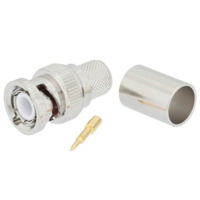
BNC Male Connector for RG8U / RG213 / LMR400 / LMR400UF / RFC400 / RFC400DB / RFC400UF cables is a robust, quick-connect RF coaxial connector specifically designed for terminating these larger, 50 Ohm impedance cables. Unlike the threaded TNC, the BNC utilizes a bayonet coupling mechanism, allowing for fast and simple connection and disconnection through a quarter-turn lock. Being a “Male” connector, it features a central pin (inner conductor) and two bayonet lugs on its outer barrel, which engage with corresponding slots on a female BNC jack. For these thicker cables, the termination typically involves a crimp method for the outer ferrule (securing the braid and jacket), while the center pin often requires soldering to ensure a high-integrity electrical connection to the larger central conductor. Its compatibility with high-performance cables like LMR400 series and traditional RG8U/RG213 indicates its use in applications demanding low signal loss and good power handling. While its bayonet coupling offers convenience, it generally has a lower maximum frequency rating and less vibration resistance compared to threaded connectors like N-Type or TNC, making it more common in applications up to a few GHz, such as test equipment, video surveillance (though often 75 Ohm BNC here), amateur radio, and some commercial communication systems where quick connect/disconnect is prioritized.
Technical Specification
1. Electrical Specifications:
- Impedance: 50Ω (Ohms). This is standard for BNC connectors used in RF applications and matches all the listed cables.
- Frequency Range: Typically 0 to 4 GHz. While some specialized BNCs can go higher, this is the common reliable range for crimp/solder types on these larger cables. The bayonet coupling can limit performance at higher frequencies compared to threaded connectors.
- Voltage Rating:
- Working Voltage: Often around 500VRMS (Volts Root Mean Square).
- Dielectric Withstanding Voltage (DWV): Typically 1500VRMS (at sea level).
- VSWR (Voltage Standing Wave Ratio):
- Good performance, typically <1.3:1 to 1.5:1 up to 3 GHz, degrading slightly towards 4 GHz.
- Contact Resistance:
- Center Contact: ≤1.5 m$\Omega$ (milliohms).
- Outer Contact: ≤1.0 m$\Omega$.
- Insulation Resistance: ≥5000 M$\Omega$ (Megaohms).
- Insertion Loss: Typically low, around <0.2 dB at lower frequencies, increasing with frequency.
2. Mechanical Specifications:
- Connector Type: BNC Male Plug.
- Coupling Mechanism: Bayonet coupling, requiring a quarter-turn to lock/unlock, allowing for quick connection/disconnection.
- Termination Style:
- Outer Ferrule: Crimp (for the cable’s outer braid and jacket).
- Center Contact (Pin): Most commonly Solder for RG8U and RG213 due to their larger solid/stranded center conductors. For LMR-400 series, some designs may use a crimp center pin, offering a fully crimp solution.
- Cable Compatibility: Designed for cables with an approximate 0.405 inch (10.3 mm) outer diameter:
- RG8U & RG213: Traditional large-diameter braided coaxial cables.
- LMR400, LMR400UF, RFC400, RFC400DB, RFC400UF: Low-loss, often double-shielded, modern equivalents.
- Durability (Mating Cycles): Typically ≥500 cycles.
- Cable Retention Force: Robust, designed to securely hold the larger cable.
3. Material & Plating:
- Body: Usually Brass, chosen for its good machinability and strength.
- Body Plating: Commonly Nickel (over copper flash) for good corrosion resistance and durability. Some higher-end versions might use Silver or Tri-Metal (Albaloy) plating for enhanced RF performance and environmental resistance.
- Center Contact: Brass (for the pin).
- Center Contact Plating: Gold (typically 30-50 microinches over nickel) for excellent conductivity, low contact resistance, and corrosion prevention.
- Insulator (Dielectric): PTFE (Polytetrafluoroethylene) is the standard choice due to its excellent RF properties (low dielectric constant, low loss) and high-temperature stability.
- Gasket/Seal (if applicable): Silicone rubber or other elastomers for environmental sealing.
4. Environmental Specifications:
- Temperature Range (Operating): Typically −55∘C to +155∘C or +165∘C, reflecting the materials’ capabilities.
- Corrosion Resistance: Good resistance to salt spray, humidity, and general environmental exposure (e.g., meeting MIL-STD-202).
- Vibration: Designed to maintain connection under moderate vibration, though threaded connectors offer superior vibration resistance.
- Shock: Engineered to withstand mechanical shock.
- Weatherproof/Waterproof: While BNCs are not inherently as weatherproof as threaded connectors, many are designed to offer good environmental resistance when properly installed. Some might achieve IP67 when mated with specific sealing boots.
5. Recommended Tooling:
- Crimp Tool: Requires a heavy-duty crimp tool with the correct hexagonal die size for the ferrule (e.g., often 0.429″ / 10.9mm for these larger cables).
- Soldering Iron & Solder: Essential if the center pin is solder-type.
- Cable Stripping Tool: A precision multi-stage stripping tool is critical for accurate cable preparation, as dimensions vary for different cable types (even within the “400 series”).


There are no reviews yet.