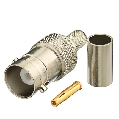
A BNC Female Connector is an RF (Radio Frequency) coaxial connector featuring a bayonet-style coupling mechanism that allows for quick and reliable connection to a corresponding male BNC connector. This female version, often referred to as a jack, is designed to be mounted on a chassis, panel, or PCB, or used as an inline adapter. While BNC connectors are available in both 50 Ohm and 75 Ohm impedances, this description refers to those compatible with commonly 50 Ohm cables such as RG58, RG142, RG223, RG400, LMR195, and RFC195. The connector typically consists of a central contact (socket) and an outer cylindrical body that mates with the male connector’s bayonet lugs. Attachment to the cable usually involves a crimp method for the outer braid and a solder or crimp method for the center conductor, ensuring robust mechanical and electrical performance. These connectors are widely used in a variety of applications including radio communication, test equipment, video surveillance, and networking, offering good performance up to several gigahertz with low insertion loss and reliable signal integrity
Technical Specification
1. Electrical Characteristics:
- Impedance: 50 Ohms (Ω)
- Frequency Range:
- Standard: DC to 4 GHz (usable up to 11 GHz with increasing VSWR/reflection)
- High Performance: DC to 6 GHz or even 12 GHz for specialized applications.
- VSWR (Voltage Standing Wave Ratio):
- Typical: ≤1.30:1 up to 4 GHz
- Better performance (e.g., ≤1.15:1) at lower frequencies (e.g., up to 1 GHz).
- Working Voltage: 500 V RMS (at sea level)
- Dielectric Withstanding Voltage: 1500 V RMS (at sea level)
- Insulation Resistance: ≥5000 M$\Omega$
- Contact Resistance:
- Center Contact: ≤1.5 m$\Omega$ (initial), ≤2.0 m$\Omega$ (after environmental testing)
- Outer Contact: ≤1.0 m$\Omega$ (initial), ≤1.5 m$\Omega$ (after environmental testing)
- RF Leakage: Typically ≥−55 dB at 3 GHz
- Insertion Loss: Low, typically ≤0.2 dB at 3 GHz
2. Mechanical Characteristics:
- Connector Style: Female (Jack/Receptacle)
- Mating Interface: BNC (Bayonet Neill-Concelman), per MIL-STD-348A/301 or IEC 61169-8
- Coupling Mechanism: Bayonet, 2-stud quick connect/disconnect (1/4 turn)
- Cable Attachment Method:
- Center Contact: Solder or Crimp (depending on design)
- Outer Braid/Ferrule: Crimp (most common for listed cables)
- Other less common methods: clamp, twist-on (for field termination).
- Cable Retention (Axial Force): Varies by cable type and termination method, typically 20-100 lbs (e.g., for crimp types)
- Durability (Mating Cycles): ≥500 cycles (standard), ≥1000 cycles (high-grade versions)
3. Materials and Finishes:
- Body: Brass, Nickel Plated (typically 100 µin min)
- Center Contact: Phosphor Bronze or Beryllium Copper, Gold Plated (typically 3-50 µin over Nickel)
- Insulators: PTFE (Polytetrafluoroethylene / Teflon) for high performance/temperature, or Delrin/PE for standard applications.
- Gaskets (where applicable): Silicone Rubber
- Crimp Ferrule: Annealed Copper or Brass, Nickel Plated
4. Environmental Characteristics:
- Operating Temperature Range:
- PTFE Insulated: −65∘C to +165∘C
- PE/Delrin Insulated: −40∘C to +85∘C
- Thermal Shock: MIL-STD-202, Method 107, Condition B
- Vibration: MIL-STD-202, Method 204, Condition D
- Mechanical Shock: MIL-STD-202, Method 213, Condition I
- Moisture Resistance: MIL-STD-202, Method 106
- Corrosion (Salt Spray): MIL-STD-202, Method 101, Condition B (48 hours)
Cable Impedance for Reference (all are typically 50 Ohms):
- RG58: 50 Ohms
- RG142: 50 Ohms
- RG223: 50 Ohms
- RG400: 50 Ohms
- LMR195: 50 Ohms
- RFC195: 50 Ohms


There are no reviews yet.